Rotor hole pushing equipment capable of avoiding excessive hole forming for three-phase motor machining

A three-phase motor and rotor technology, applied in metal processing equipment, metal processing, milling machine equipment, etc., can solve problems such as excessive opening, milling cutter detachment, weak control force of milling cutter and its rotating shaft, and improve stability , to avoid the effect of shaking

Active Publication Date: 2022-05-17
南通曦瑞电机科技有限公司
View PDF7 Cites 0 Cited by
  • Summary
  • Abstract
  • Description
  • Claims
  • Application Information

AI Technical Summary

Problems solved by technology

[0004] Aiming at the deficiencies of the prior art, the present invention provides a rotor-pushing device for machining three-phase motors that can avoid excessive drilling, which solves the problem that the conventional hole-pushing equipment generally uses software to control the milling cutter in the above-mentioned background technology. The movement track makes the hole on the surface of the rotor form a shape consistent with the track, but this method has weak control over the milling cutter and its rotating shaft. When the milling cutter rubs against the rotor surface, it is easy to cause the milling cutter to deviate from the preset track due to external force, thus Problems leading to over-drilling

Method used


Image

  • Rotor hole pushing equipment capable of avoiding excessive hole forming for three-phase motor machining
  • Rotor hole pushing equipment capable of avoiding excessive hole forming for three-phase motor machining
  • Rotor hole pushing equipment capable of avoiding excessive hole forming for three-phase motor machining

Examples


Embodiment Construction

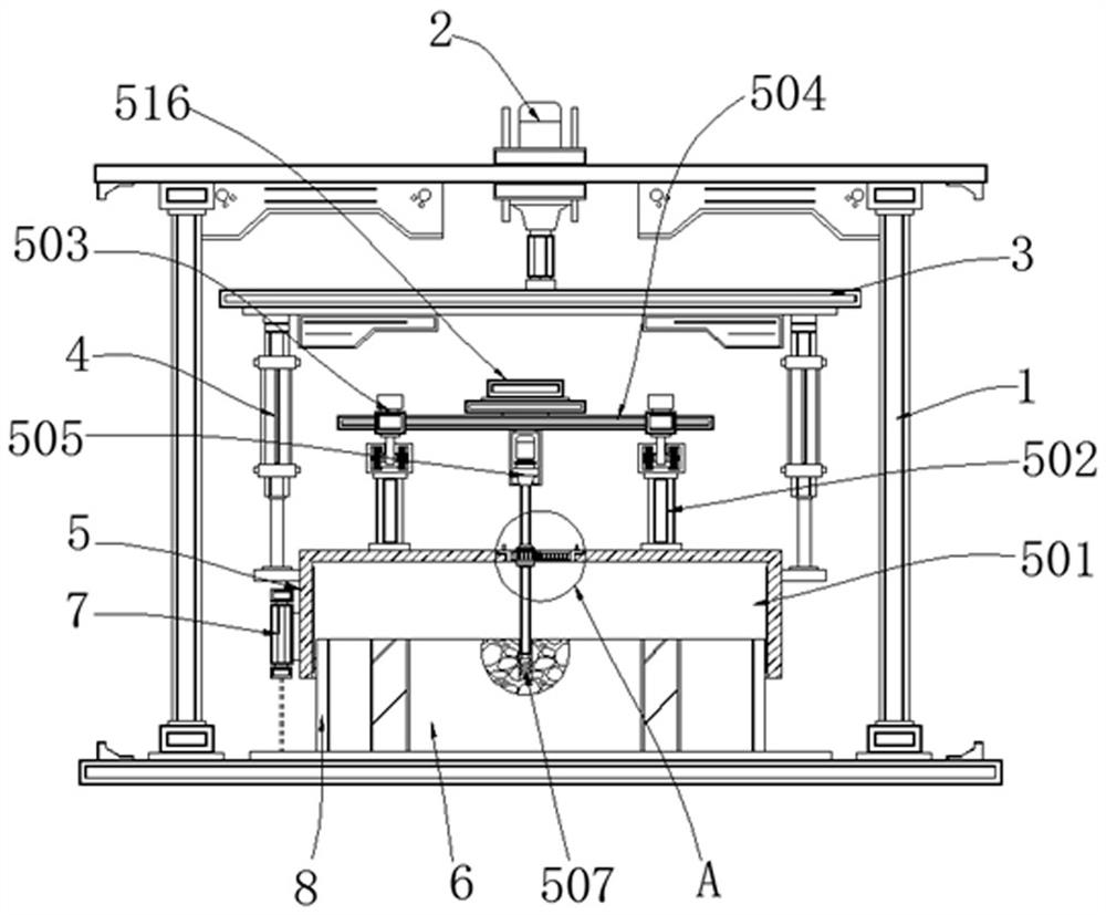
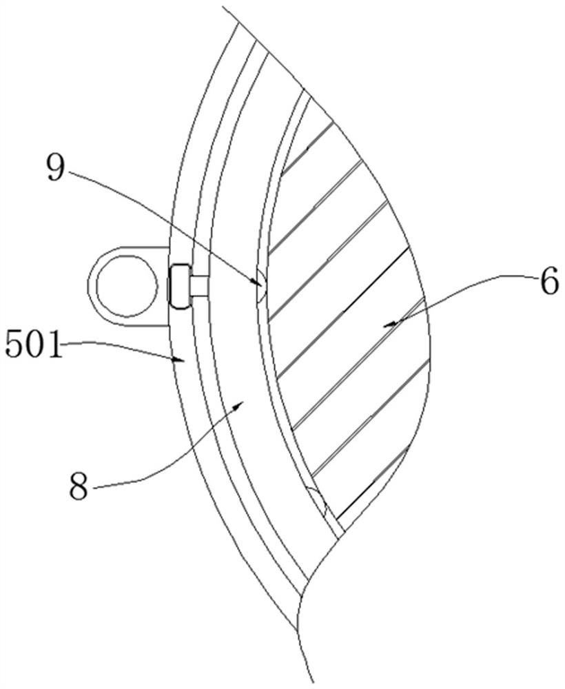
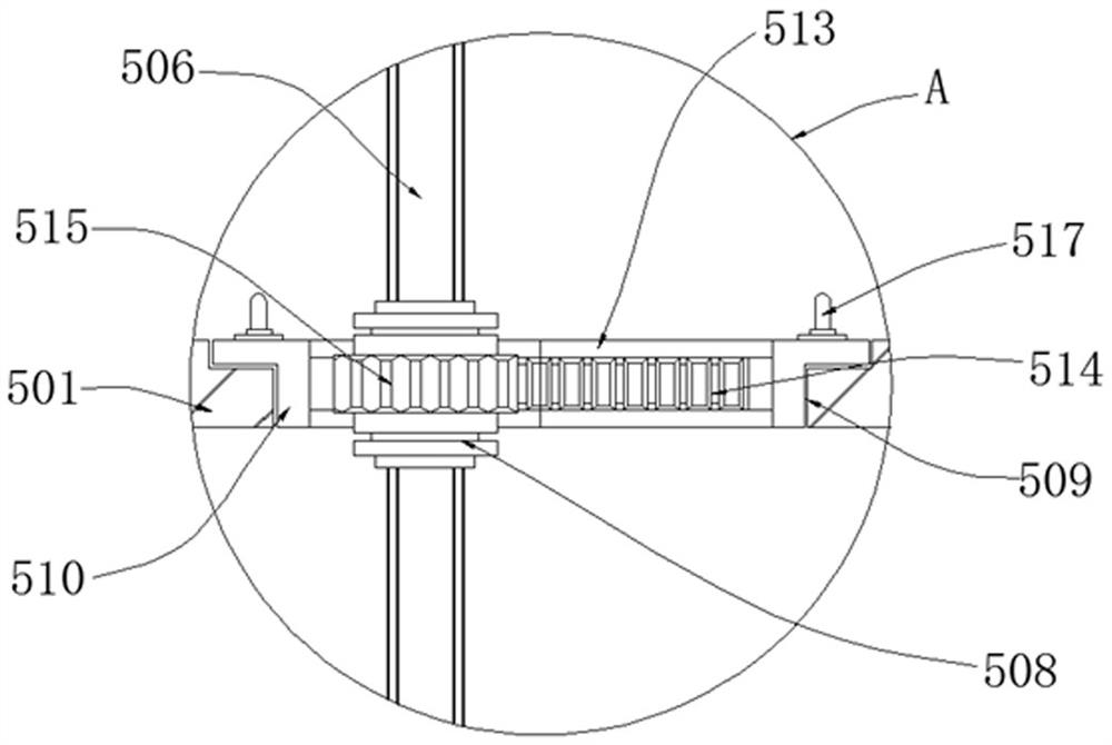
[0023] like Figure 1-5 As shown, the present invention provides a technical solution: a rotor pushing device for three-phase motor processing that can avoid excessive drilling, including a processing frame 1 and a drilling assembly 5, the top of the processing frame 1 is equipped with an adjusting motor 2, And the bottom of the adjustment motor 2 is connected with a transmission disc 3, the bottom surface of the transmission disc 3 is provided with an electric lifting rod 4, and the opening assembly 5 is fixed on the bottom of the electric lifting rod 4, and the opening assembly 5 includes a sleeve 501, a Y Shaft double slide rail 502, first block 503, second block 504, drive motor 505, rotating shaft 506, milling cutter head 507, bearing 508, placement groove 509, first shaping part 510, card slot 511, card post 512, The second shaping part 513, the tooth edge 514 of the shaping part, the connecting tooth edge 515 and the X-axis double slide rail 516, the two sides of the up...


PUM


Abstract

The invention discloses rotor hole pushing equipment capable of avoiding excessive hole forming for three-phase motor machining, and relates to the technical field of three-phase motor machining, in particular to a machining frame and a hole forming assembly, an adjusting motor is assembled at the top of the machining frame, and electric lifting rods are arranged on the two sides of the bottom face of a transmission disc. The tapping assembly is fixed to the bottom of the electric lifting rod, and a rotor body is placed at the bottom of the machining frame. According to the rotor hole pushing equipment capable of avoiding excessive hole opening for three-phase motor machining, the action track of the milling cutter head is synchronously limited from the physical level, so that the stability of the milling cutter head during moving is improved, too large hole opening caused by shaking is avoided, the distance size between the milling cutter head and the bottom of a rotor body is further measured in real time during hole opening, and the machining precision is improved. And furthermore, the milling cutter heads with different action tracks can be used by replacing the first shaping piece and the second shaping piece of the shaping piece tooth edges with different shapes, so that the milling cutter head can adapt to different trepanning shapes.

Description

technical field [0001] The invention relates to the technical field of three-phase motor processing, in particular to a rotor hole-pushing device which can avoid excessive drilling for three-phase motor processing. Background technique [0002] The rotor is an important part of a three-phase motor. The rotor of a three-phase motor is generally composed of an iron core with coils, a slip ring, and a fan blade. The surface of the rotor often has holes evenly distributed for winding, and these holes are usually It is formed by turning the milling cutter and pushing it down to stick to the surface of the rotor to open holes, and the equipment for this hole opening operation is called pushing hole equipment. [0003] The existing hole pushing equipment generally uses software to control the movement trace of the milling cutter so that the holes on the surface of the rotor form a shape consistent with the trace, but this method has weak control over the milling cutter and its shaf...

Claims


Application Information

Patent Timeline
Patent Type & Authority Applications(China)
IPC IPC(8): B23C3/00B23C9/00B23Q3/06B23Q5/34B23Q15/14B23Q17/24H02K15/02
CPCB23C3/00H02K15/02B23C9/00B23Q5/34B23Q3/06B23Q15/14B23Q17/2428Y02P70/10
Inventor 张爱娟蔡海建张浩缪徐张学森白连川
Owner 南通曦瑞电机科技有限公司
Why Eureka
Try Eureka