
Steel plate type solder paste printing mold for SMT (Surface Mount Technology)

A technology of solder paste printing and steel plate, which is applied in the direction of assembling printed circuit, printed circuit, and printed circuit manufacturing of electrical components, to achieve the effects of delaying the evaporation time, preventing short circuit, and accelerating cooling and solidification

Inactive Publication Date: 2022-05-06
梁芷欣
View PDF0 Cites 0 Cited by
  • Summary
  • Abstract
  • Description
  • Claims
  • Application Information

AI Technical Summary

Problems solved by technology

[0004] In view of the deficiencies in the use of the existing steel plate solder paste printing mold for SMT chip proposed in the background technology, the present invention provides a steel plate solder paste printing mold for SMT chip, which has the advantage of good demoulding effect , to solve the problems raised in the above background technology

Method used


Image

  • Steel plate type solder paste printing mold for SMT (Surface Mount Technology)
  • Steel plate type solder paste printing mold for SMT (Surface Mount Technology)
  • Steel plate type solder paste printing mold for SMT (Surface Mount Technology)

Examples


Embodiment Construction

[0020] The following will clearly and completely describe the technical solutions in the embodiments of the present invention with reference to the accompanying drawings in the embodiments of the present invention. Obviously, the described embodiments are only some, not all, embodiments of the present invention. Based on the embodiments of the present invention, all other embodiments obtained by persons of ordinary skill in the art without making creative efforts belong to the protection scope of the present invention.

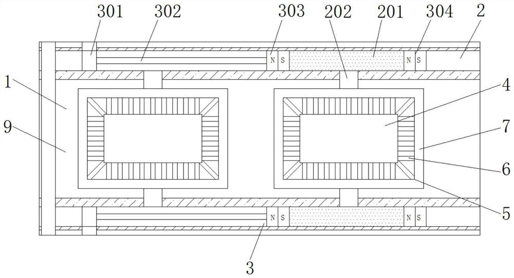
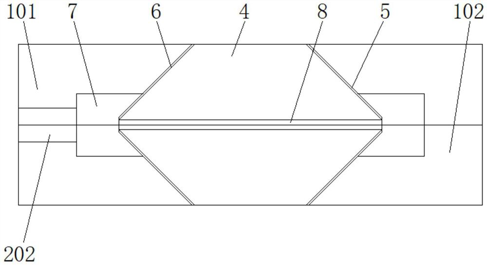
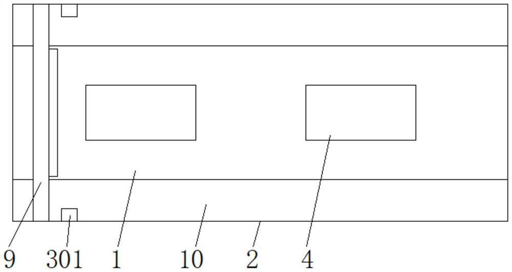
[0021] see figure 1 , a steel plate type solder paste printing mold for SMT patch, comprising a printed board body 1, a tin liquid tank 4 is opened on the outer wall of the printed board body 1, and a printing scraper 9 is slidingly connected to the surface of the printed board body 1, and the printed board body 1 is Put the tin liquid on the front side of the scraper 9, under the movement of the printing scraper 9, the tin can be hydraulically injected into t...


PUM


Abstract

The invention relates to the technical field of SMT elements, and discloses a steel plate type solder paste printing mold for SMT patching, which comprises a printing plate body, a tin liquid groove is formed in the outer wall of the printing plate body, a printing scraper blade is slidably connected to the surface of the printing plate body, the printing plate body comprises an upper plate body and a lower half body, and the upper half body and the lower half body are arranged in the printing plate body. And the upper plate body and the lower half body have the same structure and are symmetrically arranged. According to the printing plate, the edge liquid groove is formed in the periphery of the tin liquid groove of the printing plate body, a solidified scaling powder layer is formed on the outer wall of the tin liquid groove in cooperation with the liquid ring cavity, the liquid separating opening and the liquid transferring thin groove, the scaling powder layer is used for separating tin liquid paste from the outer wall of the tin liquid groove, and therefore the tin liquid paste is prevented from being attached to the outer wall of the tin liquid groove; and by utilizing the characteristic that the soldering flux can absorb heat to evaporate, a gap can be formed between the tin liquid paste and the outer wall of the tin liquid tank after the soldering flux absorbs the heat of the tin liquid paste to evaporate, so that the problem that the printing plate body is adhered to the tin liquid paste during demolding is avoided.

Description

technical field [0001] The invention relates to the technical field of chip components, in particular to a steel plate type solder paste printing mold for SMT chips. Background technique [0002] Solder paste printing is now considered to be a key process step in surface mount technology to control the quality of the final solder joint. Printing is a process based on fluid mechanics, which can be repeated many times. Glue) is coated on the surface of the PCB. Generally speaking, the printing process is very simple. The top of the PCB is kept at a certain distance from the steel plate (non-contact) or completely attached (contact), and the solder paste or glue is applied on the scraper. Under the action of the steel plate, it flows through the surface of the steel plate and fills the cuts on it, so the solder paste or glue is pasted on the surface of the PCB. Finally, the steel plate is separated from the PCB, leaving an image composed of solder paste or glue on the PCB. ...

Claims


Application Information

Patent Timeline
Patent Type & Authority Applications(China)
IPC IPC(8): H05K3/34
CPCH05K3/341
Inventor 梁芷欣
Owner 梁芷欣
Learn More