
Optical fiber ribbon optical cable

An optical fiber ribbon and cable technology, which is applied in the field of optical fiber communication, can solve the problems of increased core density, high cost, and reduced effective utilization product, and achieves the effect of high core density, less material consumption, and small product diameter.

Active Publication Date: 2022-01-28
上海新联纬讯科技发展股份有限公司
View PDF8 Cites 5 Cited by
  • Summary
  • Abstract
  • Description
  • Claims
  • Application Information

AI Technical Summary

Problems solved by technology

[0007] However, the core density of the layer-stranded optical cable in the prior art is not large, and the layer-stranded ribbon cable is large in size due to the loose tube, so the overall outer diameter of the product is large, the cost is high, it is inconvenient to strip, and it is easy to crack; The loose tube of the central bundle tube ribbon cable is located in the center, and the optical fiber ribbons are stacked in the loose tube as in the layered ribbon cable. Because the loose tube is produced, the optical fiber ribbon laminate is required. Rotating, so as to ensure the space size of the inner cavity of the loose tube, so that the optical fiber ribbon has a surplus length, so that it can be used in different temperature environments. In this way, the inner tube of the loose tube must be at least larger than the diagonal length of the optical fiber ribbon body. Therefore, the diameter cannot be reduced. In addition, the reinforcement is located outside the loose tube, and there is a protective layer on the outside. The protection layer also covers the reinforcement and there must be enough space between the outermost edge of the reinforcement and the outermost edge of the protective layer. distance, otherwise it will be twisted and cracked, etc., so the core density and cost of the central beam tube optical fiber ribbon cable are still relatively high; the skeleton type ribbon cable in the prior art lays the optical fiber ribbons in the skeleton groove Inside, as stipulated in the communication industry standard YD / T 981 of the Ministry of Posts and Telecommunications and described in the above three documents, as the number of cores of a single optical fiber increases, the width of the skeleton groove increases, and multiple skeleton grooves A very large skeleton is required at the same time, resulting in an increase in diameter and a decrease in the effective use area, so the core density needs to be improved, the cost needs to be reduced, and the diameter needs to be reduced.

Method used


Image

  • Optical fiber ribbon optical cable
  • Optical fiber ribbon optical cable
  • Optical fiber ribbon optical cable

Examples


Embodiment 1

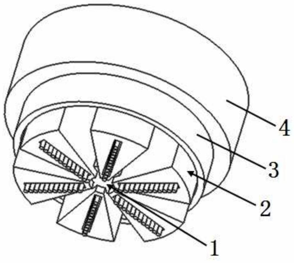
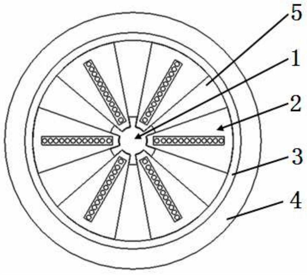
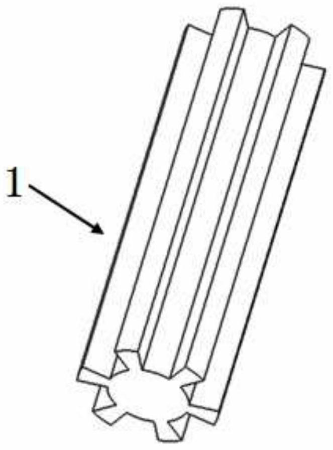
[0057] please see Figure 1 to Figure 6 , an optical fiber ribbon cable, has a skeleton part 1, a plurality of loose sleeve parts 2, a protective layer 3, and an outer sheath 4, and is characterized in that: the skeleton part 1 is composed of a skeleton body 11 and distributed outside the skeleton body 11 Consisting of a plurality of bone leaves 12, there are recessed skeleton grooves 13 between adjacent bone leaves 12, the skeleton parts are of an integrated structure, and the outer edges of all bone leaves 12 are on the same circumference; the cross section of the loose sleeve part 2 The loose tube part 2 is composed of a loose tube 21. The upper and lower sides of the loose tube 21 have a rectangular tube main cavity 23 near the center, and the main optical fiber ribbon 22 is located in the tube main cavity 23. , the length of the main cavity of the sleeve is much greater than the width, and the upper and lower symmetrical axes of the main cavity of the sleeve coincide with...

Embodiment 2

[0059] please see Figure 7 to Figure 9 ,refer to Figure 1 to Figure 6 , an optical fiber ribbon cable, has a skeleton part 1, a plurality of loose sleeve parts 2, a protective layer 3, and an outer sheath 4, and is characterized in that: the skeleton part 1 is composed of a skeleton body 11 and distributed outside the skeleton body 11 Consisting of a plurality of bone leaves 12, there are recessed skeleton grooves 13 between adjacent bone leaves 12, the skeleton parts are of an integrated structure, and the outer edges of all bone leaves 12 are on the same circumference; the cross section of the loose sleeve part 2 The loose tube part 2 is composed of a loose tube 21. The upper and lower sides of the loose tube 21 have a rectangular tube main cavity 23 near the center, and the main optical fiber ribbon 22 is located in the tube main cavity 23. , the length of the main cavity of the sleeve is much greater than the width, and the upper and lower symmetrical axes of the main c...

Embodiment 3

[0061] please see Figure 10 to Figure 13 ,refer to Figure 1 to Figure 9 , an optical fiber ribbon cable, has a skeleton part 1, a plurality of loose sleeve parts 2, a protective layer 3, and an outer sheath 4, and is characterized in that: the skeleton part 1 is composed of a skeleton body 11 and distributed outside the skeleton body 11 Consisting of a plurality of bone leaves 12, there are recessed skeleton grooves 13 between adjacent bone leaves 12, and the skeleton parts are of an integrated structure, and the outer edges of all bone leaves 12 are on the same circumference; the loose sleeve part 2 consists of a loose sleeve 21 , an upper limit part 24, and a lower limit part 25. The cross section of the loose tube 21 is fan-shaped with the top angle removed, and there is a rectangular casing main cavity 23 near the center of the upper and lower sides of the loose tube 21. The main optical fiber ribbon 22 is located in the casing main cavity 23, the length of the casing m...


PUM

PropertyMeasurementUnit
thicknessaaaaaaaaaa

Abstract

The invention belongs to the technical field of optical fiber communication, and discloses an optical fiber ribbon optical cable, which is provided with a skeleton component, a plurality of main optical fiber ribbons and a protection layer, and is characterized in that the skeleton component is composed of a skeleton body and a plurality of skeleton blades distributed outside the skeleton body, a concave skeleton groove is formed between adjacent skeleton blades, the skeleton component is of an integrated structure, the protection layer is composed of an annular column-shaped protection layer body and a plurality of groups of accommodating components which protrude inwards from the inner wall of the protection layer body, each group of accommodating components is composed of a first isolation component, a second isolation component and at least one third isolation component, at least one main optical fiber ribbon with a coating layer is arranged in each isolation groove, and the protection layer body is located outside the main optical fiber ribbon. The optical fiber ribbon optical cable has the main beneficial effects that the product diameter is smaller, the material consumption is lower, the cost is lower, the fiber core density is higher, and the optical fiber ribbon is more convenient, quicker and easier to take and place.

Description

[0001] This application is a divisional application of an invention patent application named: An optical fiber ribbon cable, application number: 2021100914120, and application date: January 23, 2021. technical field [0002] The invention belongs to the technical field of optical fiber communication, and in particular relates to an optical fiber ribbon cable. Background technique [0003] With the rapid development of information technology, the application of optical fiber and optical fiber ribbon is increasing day by day. In order to make the cost lower and the optical fiber denser, the industry has made unremitting research and development, such as the optical cable disclosed in the following documents. [0004] CN207457566U discloses a large-pitch skeleton-type optical cable, which includes a skeleton-type cable core and an outer sheath. The skeleton-type cable core includes a skeleton and an open skeleton groove arranged at intervals on the periphery of the skeleton, and...

Claims


Application Information

Patent Timeline
Patent Type & Authority Applications(China)
IPC IPC(8): G02B6/44
CPCG02B6/4407G02B6/4404G02B6/4432
Inventor 戴丽芬
Owner 上海新联纬讯科技发展股份有限公司
Learn More