


Quick Research
Generate reliable direction feasibility study reports for your R&D in just a few steps.

Technical Q&A
Discover and master advanced knowledge NOW. Basics, ideas, possibilities, all at once.

Find Solutions
As an expert in R&D theories, this can generate solutions to your technical problems instantly.

Evaluate Feasibility
Analyze your overall solution with one click, know your potential R&D risks in advance.

Monitor Landscape
Get weekly tech updates, stay abreast of the latest tech innovations and key insights.
In-situ precipitation method self-assembled core-shell structure nanoparticle modified perovskite oxide electrode material, preparation method and application thereof
A perovskite oxide, core-shell structure technology, applied in battery electrodes, structural parts, solid electrolyte fuel cells, etc., can solve problems such as poor catalytic activity, carbon deposition, particle agglomeration and growth, and achieve good controllability. Effect
- Summary
- Abstract
- Description
- Claims
- Application Information
AI Technical Summary
Problems solved by technology
Method used
Image

Examples
Embodiment 1
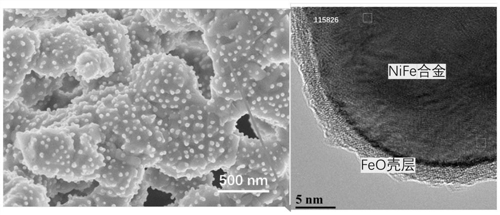
[0036] A cathode material for a solid oxide electrolytic cell with high carbon dioxide electrolysis performance, the specific structure is FeO-coated NiFe alloy core-shell structure nanoparticles modified (PrSr) 2 (NiFeMo) 2 o 6-δ Double perovskite oxide composites.
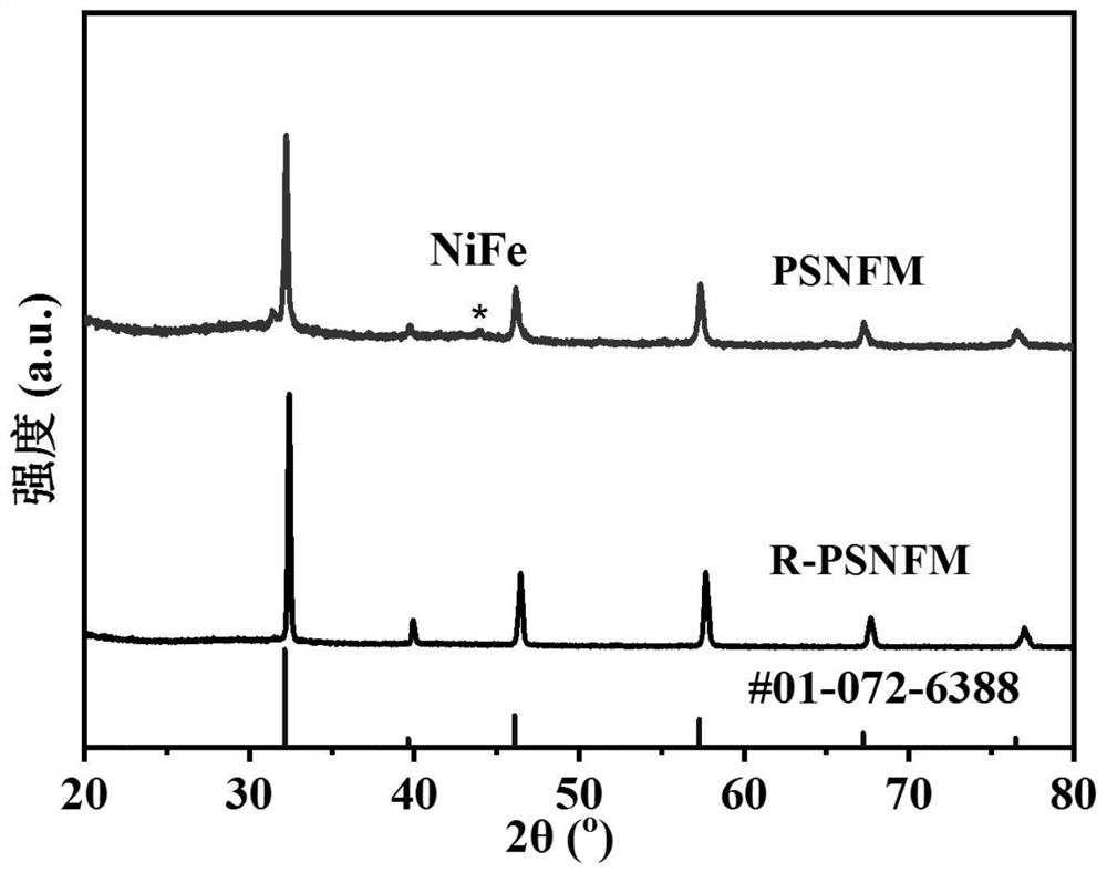
[0037] (1) Press Pr 0.4 Sr 1.6 Ni 0.2 Fe 1.3 Mo 0.5 o 6-δ (PSNFM) Stoichiometric ratio Take praseodymium nitrate, strontium carbonate, nickel nitrate, ferric nitrate and molybdenum acid and dissolve them in deionized water, then add the corresponding weight of citric acid and EDTA. Aqueous ammonia was added dropwise to adjust the pH value to 8. Stir and heat until a sol is obtained, and then dehydrate in an oven at 250° C. to obtain a xerogel. The dry gel was ground and calcined at 1200° C. for 10 h to obtain a pure-phase perovskite precursor powder. XRD analysis shows that the precursor is a phase-pure double perovskite structure, such as figure 1 shown.
[0038] (2) Place part of the powder in step...
Embodiment 2
[0045] A solid oxide fuel cell anode material with anti-coking ability, the specific structure is FeO coated NiFe alloy core-shell structure nanoparticles modified (PrSr) 2 (NiFeMo) 2 o 6-δ (R-PSNFM) double perovskite oxide composites:
[0046] (1) By solid-phase method, according to stoichiometric ratio Pr 0.4 Sr 1.6 Ni 0.2 Fe 1.3 Mo 0.5 o 6-δ (PSNFM) Weigh praseodymium oxide, strontium carbonate, nickel oxide, iron oxide and molybdenum oxide with absolute ethanol, mix them by ball milling for 24 hours, and then sinter at 1200°C for 12 hours to form a phase to obtain a perovskite precursor powder. The obtained perovskite oxide has a precursor at 900 degrees 97% H 2 -H 2 The reduction pretreatment under O atmosphere for 2 hours resulted in R-PSNFM. After surface reduction by XRD analysis, the material maintained a double perovskite structure and NiFe alloy peaks appeared. SEM analysis also shows that a large number of nanoparticles are uniformly dispersed on the surf...
Embodiment 3
[0054] A kind of solid oxide electrolytic cell cathode material with high carbon dioxide electrolysis efficiency, specific molecular formula is (Pr 0.8 Sr 1.2 ) 0.95 Ni 0.2 Fe 1.3 Mo 0.5 o 6-δ .
[0055] (1) Press (Pr 0.8 Sr 1.2 ) 0.95 Ni 0.2 Fe 1.3 Mo 0.5 o 6-δ (PSNFM) stoichiometric ratio Weigh praseodymium nitrate, strontium carbonate, nickel nitrate, ferric nitrate and molybdenum acid and dissolve them in deionized water, then add the corresponding weight of citric acid and EDTA. Aqueous ammonia was added dropwise to adjust the pH value to 8. Stir and heat until a sol is obtained, and then dehydrate in an oven at 250° C. to obtain a xerogel. The dry gel was ground and then calcined at 1200° C. for 10 h to obtain a pure-phase double perovskite precursor powder. XRD analysis showed that the precursor was a phase-pure double perovskite structure.
[0056] (2) Place part of the powder in step (1) directly under 97% H at 800°C 2 -H 2 The reduced powder (R-PSN...
PUM
 Abstract
Description
Claims
Application Information
 - R&D Engineer
- R&D Manager
- IP Professional
- Industry Leading Data Capabilities
- Powerful AI technology
- Patent DNA Extraction
Browse by: Latest US Patents, China's latest patents, Technical Efficacy Thesaurus, Application Domain, Technology Topic, Popular Technical Reports.
© 2024 PatSnap. All rights reserved.Legal|Privacy policy|Modern Slavery Act Transparency Statement|Sitemap|About US| Contact US: help@patsnap.com