A laser cutting head with variable spot track shape and its cutting process

A technology of laser cutting head and cutting process, which is applied in the field of cutting process and laser cutting head, which can solve the limitations of cutting speed, cutting thickness and cutting surface, cannot realize the change of direction in the plane, and cannot meet the requirements of wider kerf To achieve the effect of ensuring long-term operation, improving energy utilization and cutting efficiency, and increasing plate thickness and cutting speed

Active Publication Date: 2022-02-22
JINAN BODOR LASER CO LTD
View PDF9 Cites 0 Cited by
  • Summary
  • Abstract
  • Description
  • Claims
  • Application Information

AI Technical Summary

Problems solved by technology

If a focusing lens with a longer focal length is used to increase the focused spot to obtain a wider slit, it will cause the laser energy density near the focus to decrease, reduce the cutting efficiency, and also cause the laser divergence angle to decrease, resulting in slits on both sides of the focus The difference between the spot size at the thickness of the sheet and the spot size at the focal point is small, which cannot meet the requirements of wider slits at all thicknesses
The optical path structure of the current laser cutting head is as follows: figure 1 As shown, the beam emitted by the laser source passes through collimating mirrors, focusing mirrors and other structures, and the spot can only move up and down basically, and cannot change the direction in the plane.

Method used


Image

  • A laser cutting head with variable spot track shape and its cutting process
  • A laser cutting head with variable spot track shape and its cutting process
  • A laser cutting head with variable spot track shape and its cutting process

Examples


Embodiment 1

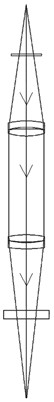
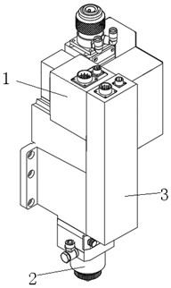
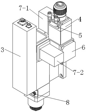
[0055] Such as Figure 2-6 As shown, a laser cutting head with variable spot trajectory shape includes a beam shaper 4, a trajectory control component, a focusing component and a nozzle arranged in sequence along the optical path direction, and the beam shaper 4 includes a beam filter component and a collimating lens component, In the direction of the light path, the beam filter assembly is positioned in front of the collimator assembly, the beam shaper 4 is equipped with an upper protective mirror 5, and the upper protection mirror 5 is located between the beam filter assembly and the collimator assembly, and the external device of the track control assembly There is a sheet metal housing 1 .

[0056] The middle part of the beam filtering component is provided with a beam passing hole, and a conical beam absorbing surface is arranged above the beam passing hole. The tapered beam absorption surface can be set according to the requirements. Through this setting, the high-ener...

Embodiment 2

[0070] The structure of the laser head of this embodiment is basically the same as that of Embodiment 1, the difference is that in the track control assembly of this embodiment, in the direction of the optical path, the Y-axis vibrating mirror 705-2 is located in front of the X-axis vibrating mirror 705-1, The reflector 6 is located behind the X-axis vibrating mirror 705-1, and the reflective surface of the reflector 6 is inclined downward;

[0071] Based on this setting, the optical path structure in this embodiment is as follows Figure 10 As shown, the laser beam emitted by the laser source passes through the beam filter assembly to filter out the stray light of the optical fiber, and then enters the collimator assembly through the upper protective mirror. The collimator 11 shapes the diffused beam into a parallel beam, and the beam hits the Y On the oscillating mirror 705-2, the Y-axis galvanometer 705-2 is reflected to the X-axis galvanometer 705-1, and the X-axis galvano...

Embodiment 3

[0073] It is suitable for laser cutting machines where the optical fiber interface of the laser source is set horizontally. No reflector is provided in the trajectory control component of this embodiment, and the optical fiber interface is inserted horizontally into the beam shaper. In this embodiment, the optical path is as follows Figure 11 As shown, the beam processed by the beam shaper at this time is directly projected on the X-axis galvanometer 705-1, reflected by the X-axis galvanometer 705-1 to the Y-axis galvanometer 705-2, and then focused by the focusing mirror 15 and The cutting laser is output from the nozzle through the lower protective mirror 8, and the control principle of the spot track is the same as that of the first embodiment.


PUM


Abstract

The invention relates to a laser cutting head with a variable shape of a light spot track and a cutting process, belonging to the field of laser cutting processing. Its technical solution is a laser cutting head with a variable spot track shape, including a beam shaper, a track control component and a focusing component arranged in sequence along the direction of the optical path. The track control component includes a reflector, an X-axis vibrating mirror and a Y-axis vibrating mirror. Mirror, the rotation axis of the X-axis galvanometer is the vertical axis, the rotation axis of the Y-axis galvanometer is the horizontal axis, the reflection surface of the mirror is opposite to the reflection surface of the X-axis galvanometer, and the reflection surface of the Y-axis galvanometer is opposite to the X-axis The reflective surfaces of the galvanometers face each other. The beneficial effect of the present invention is that, by controlling the swing of the X-axis vibrating mirror and the Y-axis vibrating mirror, in the process of laser cutting by moving the main body of the laser head, the light spot is controlled to do circular reciprocating movement in the horizontal plane, so that the existing power laser can Achieve higher power cutting effect and speed, reduce production purchase cost.

Description

technical field [0001] The invention relates to the field of laser cutting processing, in particular to a laser cutting head with a variable shape of a spot track and a cutting process. Background technique [0002] Laser cutting uses a focused high-power-density laser beam to irradiate the metal sheet to rapidly melt, gasify, ablate or reach the ignition point, and at the same time blow off the molten material with the help of a high-speed airflow coaxial with the beam, thereby realizing the metal sheet. cutting. Compared with plasma cutting, flame cutting, wire cutting and other methods, laser cutting has the advantages of small heat-affected zone, fast cutting speed and good cutting quality, and has been widely used in sheet metal cutting. Moreover, laser cutting has higher requirements on the cutting precision of the beam, such as 0.1mm, and laser cutting needs to consider issues such as slits and timely discharge of molten metal, otherwise problems such as blast holes ...

Claims


Application Information

Patent Timeline
Patent Type & Authority Patents(China)
IPC IPC(8): B23K26/38B23K26/70
CPCB23K26/38B23K26/702B23K26/703B23K26/082B23K26/064B23K2103/04B23K2103/10B23K2103/12
Inventor 杨绪广张成顺陈传明张钦溟牛满钝马驰贾文琪李伟张永泽
Owner JINAN BODOR LASER CO LTD
Why Eureka
Try Eureka