Semiconductor thermopile precise temperature control liquid cooling source system

A semiconductor, liquid cooling source technology, applied in cooling/ventilation/heating renovation, electrical components, electrical equipment structural parts, etc. The effect of convenient hot switching and simple system structure

Pending Publication Date: 2021-11-16
安徽中科新源半导体科技有限公司
View PDF0 Cites 0 Cited by
  • Summary
  • Abstract
  • Description
  • Claims
  • Application Information

AI Technical Summary

Problems solved by technology

[0005] The biggest obstacle restricting the application of semiconductor thermoelectric refrigeration technology is the low energy efficiency ratio (energy efficiency ratio = cooling capacity / power consumption), relatively high primary investment and operating costs, such as figure 2 Shown is a block diagram of the structure and principle of the air-cooled semiconductor refrigeration system. Its working principle is to transfer the thermal load of the controlled object to the B terminal 1B of the thermal pile through the semiconductor thermal pile, and then release it to the environment (outdoor air). This type of semiconductor thermoelectric The refrigeration energy efficiency ratio of the refrigeration system is usually between 0.5 and 0.9, which is much lower than the energy efficiency ratio of the vapor compression refrigeration system in the same temperature range of 2.4 to 3.0

Method used


Image

  • Semiconductor thermopile precise temperature control liquid cooling source system
  • Semiconductor thermopile precise temperature control liquid cooling source system
  • Semiconductor thermopile precise temperature control liquid cooling source system

Examples


Embodiment Construction

[0031] Below in conjunction with the accompanying drawings, the present invention will be further described through embodiments.

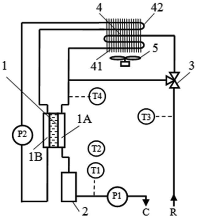
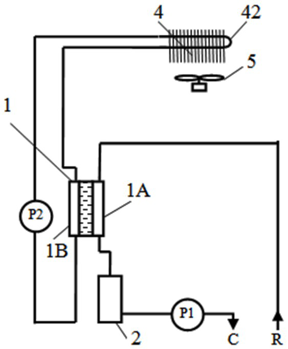
[0032] see figure 1 , a semiconductor thermopile precision temperature control liquid cold source system includes a semiconductor thermopile 1, a liquid reservoir 2, a three-way valve 3, an air heat exchanger 4, a fan 5, a first liquid pump P1 and a second liquid pump P2, The improvement lies in: using the semiconductor thermal stack 1 as the cold and heat source, the first heat exchange pipeline 41 with the three-way valve 3 and the air heat exchanger 4 constitutes a natural cooling branch (compared with figure 2 ), its function is to release the heat load of the controlled object directly to the outdoor air by using the natural temperature difference between the first circulating fluid and the outdoor low-temperature air by using the outdoor air as the natural cooling source when the outdoor temperature is low, that is, to realize natural coolin...


PUM


Abstract

The invention relates to a semiconductor thermopile precise temperature control liquid cooling source system, and belongs to the technical field of refrigeration and man-machine environment engineering. The system comprises a semiconductor thermopile, a liquid accumulator, a three-way valve, an air heat exchanger, a fan, a first liquid pump and a second liquid pump; two circulating liquid working loops are formed by two heat exchange channels of the semiconductor thermopile; when the outdoor air temperature is low, the outdoor air serves as a natural cold source, the natural temperature difference between the first circulating liquid and the outdoor low-temperature air is utilized, the thermal load of a controlled object is directly released to the outdoor air, and natural cooling is achieved. According to a real-time state, four working modes, namely thermoelectric refrigeration, natural cooling and thermoelectric refrigeration, natural cooling and semiconductor heating are operated in order, the refrigerating capacity or heating capacity is accurately controlled, and the liquid supply temperature is accurately controlled. The system of the invention is a thermoelectric refrigeration and natural cooling composite thermal control system which is suitable for all-weather working environment temperature precision control of optical, electrical, microwave and electromagnetic systems, precision machining equipment and the like.

Description

technical field [0001] The invention belongs to the technical field of refrigeration and human-machine environment engineering, and specifically relates to a liquid cooling source system for realizing precise temperature control of photoelectric or mechanical equipment working in a wide temperate climate condition of -40 to 60°C. Background technique [0002] Electronic warehouses of vehicles, photoelectric, magnetoelectric and microwave equipment, precision machining machinery and equipment, etc. all have the requirement of working in all-weather and wide temperature range, and usually have the characteristics of high heat flux density and frequent changes in heat load. This type of equipment not only needs cooling, but also needs heating in cold seasons or cold starts, and even has high requirements for the response speed and temperature control accuracy of the thermal control system, in order to improve the stability, reliability, accuracy, and maneuverability of its work....

Claims


Application Information

Patent Timeline
Patent Type & Authority Applications(China)
IPC IPC(8): H05K7/20
CPCH05K7/20H05K7/20136H05K7/20272H05K7/20327
Inventor 王铁军熊绎汪玉成王晓波
Owner 安徽中科新源半导体科技有限公司
Why Eureka
Try Eureka