
Cutting balloon with flexible cutting device

A technology for cutting balloons and cutting devices, which is applied in the fields of endoscopic cutting instruments, medical science, surgery, etc. It can solve the problems of narrowing the scope of use, weak support and poor passability of folding or helical structure cutting, and achieve the function of avoiding cutting Structural failure or detachment, preventing damage to the vessel wall, and improving the safety of the device

Pending Publication Date: 2021-11-02
山西白求恩医院 +1
View PDF4 Cites 2 Cited by
  • Summary
  • Abstract
  • Description
  • Claims
  • Application Information

AI Technical Summary

Problems solved by technology

However, the cutting balloons currently on the market have poor passability, and it is difficult to reach the lesion through complex and tortuous blood vessels for cutting. In addition, the cutting device of some products has poor cutting effect and cannot effectively open the lesion.
[0004] The Chinese patent with the application number CN201510305053.9 discloses a cutting balloon, by axially installing several rows of blades on the outer peripheral surface of the balloon, and there is a certain gap between adjacent two blades in each row of blades, although The passability is properly optimized, but the blade used for cutting the balloon has high hardness, and the blade part is not easily deformed, so it cannot pass through relatively complicated and tortuous blood vessels, which greatly reduces the scope of use, and the blade tip is too sharp. The balloon and the vessel wall are easily damaged during repeated balloon expansion and withdrawal
[0005] The Chinese patent with the application number CN201710959019.2 discloses a vascular plaque cutting device. There are circular, arc-shaped, triangular cutting wire structures outside the balloon, and the cutting wire extends to the proximal end of the balloon. It is fixed here with the distal end. Although it avoids the falling off and slipping of the cutting wire during the balloon expansion and cutting process, it greatly reduces the flexibility of the entire balloon, especially the hardening of the head, which makes it impossible to pass through the relatively complicated and tortuous The scope of use is greatly reduced, and due to the sclerosis of the head, the balloon is easy to damage the vessel wall during advancement and withdrawal
[0006] The Chinese patent with the application number CN201810478242.X discloses a cutting balloon and a balloon catheter. A flexible cutting wire is arranged on the surface of the cutting balloon. The cutting wire can be a folded structure or a helical spring structure as a whole. The folded or helical structure of the wire has good flexibility, but the single folded or helical structure has weak cutting support, and it is easy to collapse and fail during the balloon expansion cutting process, and the expected cutting effect cannot be achieved.
[0007] The Chinese patent with the application number CN202011597035.X discloses a fully developed cohesive blood vessel stenosis expansion balloon. There are multiple expansion cutting structures longitudinally arranged on the surface of the cutting balloon. The expansion cutting structure includes a hollow cutting wire and a The development support structure in the cutting wire improves the development effect but sacrifices flexibility, and cannot pass through relatively complex and tortuous blood vessels, which greatly reduces the scope of use; at the same time, the balloon expansion cutting structure is connected to the balloon alone to effectively connect the contact surface Small size, easy to cause the cutting structure to fall off from the balloon, seriously affecting the safety of the product

Method used


Image

  • Cutting balloon with flexible cutting device
  • Cutting balloon with flexible cutting device
  • Cutting balloon with flexible cutting device

Examples


Embodiment 1

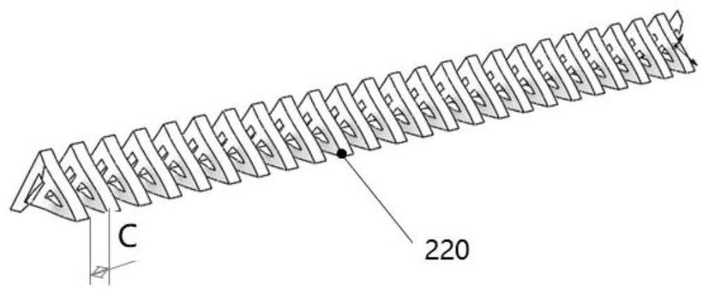
[0073] Such as figure 1 , Figure 7 As shown, the flexible cutting device 200 of the present invention consists of a cutting functional structure 220 and a flexible functional structure 210, and is installed on the balloon body 100. The 200 flexible cutting device has a width of 1mm, a height of 0.4mm, and a length of 60mm; the 220 cutting functional structure is a jagged nickel-iron alloy T-shaped elastic structure with a width of 0.6mm, a height of 0.4mm, a length of 55mm, and a thickness of 0.35mm. The width of the sawtooth is 3mm, the distance between adjacent teeth is 0.8mm, such as Figure 6 As shown; the material of the 210 flexible functional structure is silica gel covering the surface of the cutting functional structure. The width of the silicone is 0.5mm, the height is 0.4mm, and the length is 58mm. The outer surface constitutes a cutting balloon, and the tensile strength measured between the flexible cutting structure and the balloon body is 6.8N / mm after fixatio...

Embodiment 2

[0077] Such as figure 1 and Figure 9 As shown, the flexible cutting device 200 of the present invention consists of a cutting functional structure 220 and a flexible functional structure 210, and is installed on the balloon body 100. The 200 flexible cutting device has a width of 1.5mm, a height of 0.8mm, and a length of 80mm; the 220 cutting functional structure is a nickel-iron alloy triangular wire-wound elastic structure with a width of 1.0mm, a height of 0.82mm, and a length of 75mm. Figure 10 , Figure 11 Medium 220, the diameter of the winding wire is 0.06, and the gap between the winding wires is 0.2mm; firstly, the 220 cutting functional structure is evenly installed on the outer surface of the 100 balloon body, and then the 220 is cut with 210 flexible functional structure, specifically acrylic anaerobic adhesive The functional structure was filled and vacuum cured for more than 3 minutes, so that the flexible cutting device was fixed on the outer surface of the ...

Embodiment 3

[0081] Such as figure 1 and Figure 9 As shown, the flexible cutting device 200 of the present invention consists of a cutting functional structure 220 and a flexible functional structure 210, and is installed on the balloon body 100. 200 flexible cutting device width 0.8mm, height 0.4mm, length 20mm, section such as Figure 11 As shown; 220 cutting function structure is a stainless steel triangular pipe with a thickness of 0.06mm, which is cut into a width of 0.5mm, a height of 0.39mm, and a length of 17mm, and the gap is 0.02mm. image 3 The above-mentioned spring structure; the material of the flexible functional structure is silica gel with good elasticity and there is a triangular gap in the middle. The gap is an equilateral triangle with a height of 0.15 mm. The outer surface of the balloon constitutes a cutting balloon, and the tensile strength between the flexible cutting structure and the balloon body is measured to be 5.8N / mm after fixation 2 .

[0082] First pus...


PUM

PropertyMeasurementUnit
Tensile strengthaaaaaaaaaa
Widthaaaaaaaaaa
Heightaaaaaaaaaa

Abstract

The invention provides a cutting balloon with a flexible cutting device. The cutting balloon comprises a balloon body; a flexible cutting device longitudinally arranged along the outer surface of the balloon body, wherein the flexible cutting device comprises a cutting function structure and a flexible functional structure wrapping or semi-wrapping the cutting function structure; the mechanical property of the cutting functional structure is higher than that of the flexible functional structure. Compared with the prior art, the cutting balloon provided by the invention has higher flexibility, can smoothly pass through a complex tortuous blood vessel, quickly reach a preset part, prevent a blood vessel wall from being damaged and improve the instrument safety, and after pressurization, the flexible cutting device is in contact with tissues, and the flexible functional structure is extruded to enable the cutting structure to protrude. Therefore, the cutting balloon has good cutting performance, the cutting structure can be effectively fixed to the balloon through the flexible functional structure, and the phenomenon that the cutting functional structure loses efficacy or falls off in a using process of the balloon is avoided.

Description

technical field [0001] The invention belongs to the technical field of balloons, in particular to a cutting balloon with a flexible cutting device. Background technique [0002] Interventional medicine is guided by imaging medicine (X-ray, ultrasound, CT), through percutaneous puncture or through the original orifice of the human body, inserting a special catheter or instrument into the lesion for imaging, diagnosis and treatment. Because of its advantages of less trauma, fewer complications and wide application range (applicable to cardiovascular and cerebrovascular, peripheral vascular tumors or non-vascular fields, etc.), it has become the third major clinical treatment method. [0003] At present, the minimally invasive interventional therapy balloon catheter widely used clinically has limited curative effect on intravascular embolism, especially calcified lesions, especially for in-stent restenosis. Cutting balloons appearing on the market in recent years can cut plaqu...

Claims


Application Information

Patent Timeline
IPC IPC(8): A61B17/32
CPCA61B17/320016
Inventor 陈花翁玉麟刘宝瑞石全刘静怡牛冬子
Owner 山西白求恩医院
Learn More