
Metal material machining device

A processing device and metal material technology, applied in the direction of metal processing equipment, metal processing machinery parts, sawing machine devices, etc., can solve problems that affect the use, cannot improve work efficiency, and rod body size error

Inactive Publication Date: 2021-07-30
宿迁小鲤工业设计有限公司
View PDF0 Cites 0 Cited by
  • Summary
  • Abstract
  • Description
  • Claims
  • Application Information

AI Technical Summary

Problems solved by technology

[0004] The object of the present invention is to provide a metal material processing device to solve the problem that the traditional cutting of the metal material rod body proposed in the above background technology is carried out by manual feeding, so that the size of the rod body needs to be measured, and then its Fix it and then cut it, resulting in many steps and unable to improve work efficiency, and it is time-consuming and labor-intensive when feeding manually. The measured size is not necessarily accurate, which leads to errors in the size of the cut rod body, which affects subsequent use, which is not conducive to the present. The needs of metal material processing and production

Method used


Image

  • Metal material machining device
  • Metal material machining device
  • Metal material machining device

Examples


Embodiment Construction

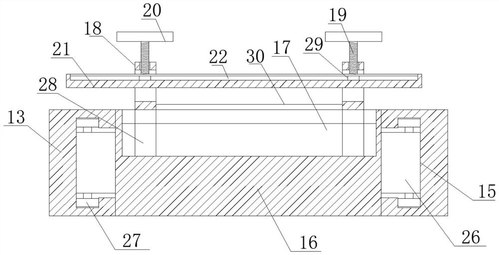
[0027] see figure 1, in an embodiment of the present invention, a metal material processing device includes a fixed base plate 1, a support pole 2 is welded vertically downward on the bottom surface of the fixed base plate 1, a control panel 3 is welded obliquely on one side of the fixed base plate 1, and the fixed base plate The top surface of 1 is welded with a fixed top block 4, and the inner side of the fixed top block 4 is horizontally provided with an extrusion plate 5, and the top surface bolt of the fixed top block 4 is connected with a pushing cylinder 6, and the number of supporting vertical rods 2 is Four, and four support vertical rods 2 are arranged parallel to each other, and the tops of the four support vertical rods 2 are fixed vertically upwards at the four corners of the bottom surface of the fixed base plate 1, and the fixed top block 4 is buckled and fixedly arranged on the fixed top. The top surface of the bottom plate 1 is close to one side, the extruding...


PUM


Abstract

The invention discloses a metal material machining device, and relates to the field of metal materials. The metal material machining device comprises a fixed bottom plate, wherein supporting vertical rods are vertically and downwards welded to the bottom face of the fixed bottom plate; a control panel is obliquely welded to one side edge of the fixed bottom plate; a fixed top block is welded to the top face of the fixed bottom plate; an extrusion plate is horizontally arranged on the inner side edge of the fixed top block; a pushing and pressing air cylinder is connected to the top face of the fixed top block through a bolt; bottom sleeve rods are vertically and upwards welded to the top face of the fixed bottom plate; extending vertical rods are vertically and upwards inserted into the top ends of the bottom sleeve rods; a top box body is horizontally welded to the side edge between the extending vertical rods; and extending side rods are vertically and downwards welded on the bottom surface of the top box body. According to the device provided by the invention, the design is integrated, the structure is simple, operation is convenient, product discharging is faster and more efficient by adopting the intelligent automatic measuring and cutting procedure, meanwhile, labor input is greatly reduced in a more time-saving and labor-saving mode, and the requirement for market development is met.

Description

technical field [0001] The invention relates to the technical field of metal material processing, in particular to a metal material processing device. Background technique [0002] Metal materials refer to materials with luster, ductility, easy conduction, heat transfer and other properties. Generally divided into ferrous metals and non-ferrous metals. Ferrous metals include iron, chromium, manganese, etc. Among them, steel is the basic structural material, known as the "skeleton of industry". Due to the advancement of science and technology and the wide application of various new chemical materials and new non-metallic materials, the substitutes for steel are increasing, and the demand for steel is relatively declining. But so far, the dominant position of steel in the composition of industrial raw materials is still difficult to replace. [0003] When processing metal materials, the current metal rod body needs to be cut into the required size to assemble the required ...

Claims


Application Information

Patent Timeline
IPC IPC(8): B23D49/00B23D51/04B23Q17/24
CPCB23D49/00B23D51/043B23Q17/2414
Inventor 葛逸
Owner 宿迁小鲤工业设计有限公司
Learn More