
Winding device for copper alloy battery core wire

A technology of a winding device and a battery core, which is applied in the directions of transportation and packaging, transportation of filamentous materials, and processing of thin materials, can solve the problems of difficulty in calculating the length of copper alloy wires, no cutting function, and cumbersome operation, and achieves structural Smart, easy-to-implement, simple-to-operate effects

Active Publication Date: 2020-03-27
WUHU CHUJIANG ALLOY COPPER
View PDF13 Cites 0 Cited by
  • Summary
  • Abstract
  • Description
  • Claims
  • Application Information

AI Technical Summary

Problems solved by technology

[0003] During the processing of copper alloy wire, the copper alloy wire is often wound in the winding device. The operation method is often to fix the wire end of the copper alloy wire on the winding device, and then rotate the winding device to roll the copper alloy wire. stacked together, and finally, transported to the warehouse by a transfer vehicle; however, the existing copper alloy wire end fixing method often fastens the end of the wire to the lug on the winding device, which is cumbersome to operate and is difficult for thicker copper Alloy wires are inconvenient to fasten; on the other hand, during the use of high-performance electrical components, because copper alloy wires need to connect electrical components at different positions, it is necessary to cut copper alloy wires into different lengths. However, the existing The copper alloy wire winding device does not have the cutting function, and it is difficult to calculate the length of the copper alloy wire

Method used


Image

  • Winding device for copper alloy battery core wire
  • Winding device for copper alloy battery core wire

Examples


Embodiment Construction

[0030] In order to clearly and completely describe the purpose, technical solution, and advantages of the present invention, the embodiments of the present invention will be further described in detail below in conjunction with the accompanying drawings. It should be understood that the specific embodiments described here are part of the embodiments of the present invention, rather than all embodiments, and are only used to explain the embodiments of the present invention, and are not intended to limit the embodiments of the present invention. All other embodiments obtained under the premise of creative work all belong to the protection scope of the present invention.

[0031] In the description of the present invention, it should be noted that the terms "center", "middle", "upper", "lower", "left", "right", "inner", "outer", "top", "bottom" ", "side", "vertical", "horizontal" and other indicated orientations or positional relationships are based on the orientations or positio...


PUM


Abstract

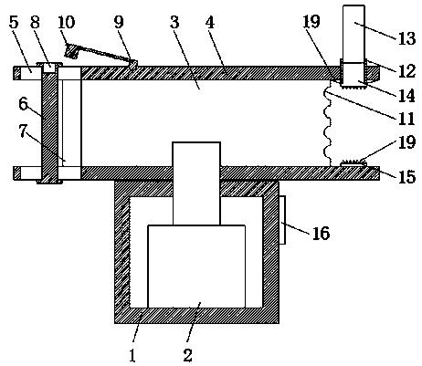
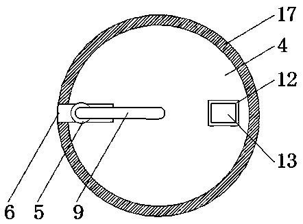
The invention relates to the technical field of copper alloy wire processing, in particular to a winding device for a copper alloy battery core wire. The winding device comprises a shell, an electricmotor is fixedly arranged in the shell, a disc is in threaded connection with an output shaft of the motor, cover plates are fixedly arranged on the upper end surface and the lower end surface of thedisc correspondingly, and a sliding groove is formed in the cover plate. A pressing rod is slidably arranged in the sliding groove. The upper end surface of the pressing rod is provided with a secondfixing groove. The upper end surface of the cover plate located on the upper side is rotatably provided with a locking piece. The lower end surface of the locking piece is integrally provided with a fixing plug matched with the second fixing groove. A sliding rail is fixedly arranged in the disc located on the upper side. A sliding plate is slidably arranged on the inner wall of the sliding rail.A first cutting tool is fixedly arranged on the lower end surface of the sliding plate. A length scale line is fixedly arranged at the edge of the upper end surface of the disc located on the upper side. The winding device is ingenious in structure, facilitates the fixing of a wire head of the copper alloy wire, and has the functions of both cutting and copper alloy wire length calculating.

Description

technical field [0001] The invention relates to the technical field of copper alloy wire processing, in particular to a winding device for copper alloy battery core wires. Background technique [0002] Copper alloy is an alloy composed of pure copper as the base and adding one or several other elements. It is mainly used to make electrical equipment such as generators, busbars, cables, switchgear, transformers, heat exchangers, pipes, and solar heating devices. Heater and other heat conduction equipment. [0003] During the processing of copper alloy wire, the copper alloy wire is often wound in the winding device. The operation method is usually to fix the wire end of the copper alloy wire on the winding device, and then rotate the winding device to roll the copper alloy wire. are stacked together, and finally transported to the warehouse by a transfer vehicle; however, the existing copper alloy wire end fixing method often fastens the end of the wire to the lug on the win...

Claims


Application Information

Patent Timeline
Patent Type & Authority Applications(China)
IPC IPC(8): B65H54/54B65H57/04B65H61/00B21F11/00
CPCB65H54/54B65H57/04B65H61/00B21F11/00B65H2701/36
Inventor 俞龙
Owner WUHU CHUJIANG ALLOY COPPER
Learn More