
Ink-jet printing perovskite light-emitting diode device based on introduction of dielectric layer and preparation method of ink-jet printing perovskite light-emitting diode device

A light-emitting diode and inkjet printing technology, which is applied in semiconductor/solid-state device manufacturing, electrical solid-state devices, semiconductor devices, etc., can solve the problem of uneven morphology of perovskite printed by inkjet printing, so as to suppress adverse effects and induce vertical Effect of growth and reduction of leakage current

Inactive Publication Date: 2021-07-23
SUZHOU UNIV
View PDF4 Cites 1 Cited by
  • Summary
  • Abstract
  • Description
  • Claims
  • Application Information

AI Technical Summary

Problems solved by technology

[0004] The purpose of the present invention is to provide a method for preparing patterned and large-area PeLEDs by direct inkjet printing of perovskite precursor solution, and by introducing a polymer insulating medium layer between the perovskite layer and the transport layer to solve the problem of spraying. The problem of uneven morphology of ink-printed perovskite, and the dielectric layer can regulate the crystallization of perovskite and suppress the leakage current, thereby improving the performance of inkjet printed PeLEDs

Method used


Image

  • Ink-jet printing perovskite light-emitting diode device based on introduction of dielectric layer and preparation method of ink-jet printing perovskite light-emitting diode device
  • Ink-jet printing perovskite light-emitting diode device based on introduction of dielectric layer and preparation method of ink-jet printing perovskite light-emitting diode device
  • Ink-jet printing perovskite light-emitting diode device based on introduction of dielectric layer and preparation method of ink-jet printing perovskite light-emitting diode device

Examples


Embodiment 1-5

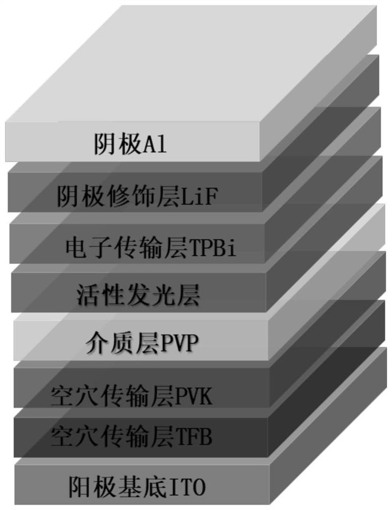
[0048] This embodiment provides an inkjet printing perovskite light emitting diode, such as figure 1 As shown, it includes an anode substrate (thickness is 150nm), hole transport layer (thickness is 40nm), insulating medium layer, active light-emitting layer (thickness is 40nm), electron transport layer (thickness is 40nm) arranged in sequence from bottom to top. 40nm), cathode modification layer (thickness is 2nm) and cathode (thickness is 100nm).

[0049] The above-mentioned method for inkjet printing perovskite light-emitting diodes comprises the following steps:

[0050] 1. Add 0.2mmol PbBr 2 , 0.2mmol CsBr, 0.08mmol PEABr were added to the solution containing crown ether (3.5mg ml -1 ) and PEO (0.3mg ml -1 ) in DMSO (1ml), and stirred at 60°C for 2 hours to obtain a perovskite precursor ink. TFB was dissolved in chlorobenzene solution at a concentration of 8 mg / ml, PVK was dissolved in toluene solution at a concentration of 4 mg / ml, and PVP was dissolved in isopropano...


PUM

PropertyMeasurementUnit
thicknessaaaaaaaaaa
thicknessaaaaaaaaaa
thicknessaaaaaaaaaa

Abstract

The invention discloses an ink-jet printing perovskite light-emitting diode device based on introduction of a dielectric layer. The ink-jet printing perovskite light-emitting diode device comprises a substrate, a hole transport layer, an insulating dielectric layer, an active light-emitting layer, an electron transport layer, an electrode modification layer and an electrode, or comprises a substrate, an electron transport layer, an insulating dielectric layer, a perovskite light absorption layer, a hole transport layer, an electrode modification layer and an electrode which are arranged in sequence, wherein the material of the insulating dielectric layer comprises one or more of polyvinylpyrrolidone, polydimethylsiloxane, polyethylene glycol terephthalate, polymethyl methacrylate, polyvinylidene fluoride and polyacrylonitrile, and the active light-emitting layer is obtained by ink-jet printing of perovskite on the insulating dielectric layer. According to the invention, the polymer insulating dielectric layer is introduced, so that the problem of non-uniform morphology of perovskite in ink-jet printing is solved; and the dielectric layer has the effects of adjusting crystallization of perovskite and inhibiting leakage current, so that the performance of ink-jet printing PeLEDs is improved.

Description

technical field [0001] The invention relates to the technical field of optoelectronic devices, in particular to an ink-jet printing perovskite light-emitting diode device based on the introduction of a dielectric layer and a preparation method thereof. Background technique [0002] In recent years, the performance of perovskite light-emitting diodes has been rapidly improved with people's unremitting efforts in material properties and device structure innovations. However, at present, laboratories mostly use the method of spin coating to prepare perovskite light-emitting diodes, which cannot meet the commercial demand for large-area and patterned production. Inkjet printing is a powerful technique for realizing large-area, patterned, pixelated perovskite light-emitting diodes. [0003] At present, researchers mostly use inkjet printing technology to prepare various perovskite photoluminescence (PL) patterns for anti-counterfeiting marks, encryption, display, laser and other...

Claims


Application Information

Patent Timeline
Patent Type & Authority Applications(China)
IPC IPC(8): H01L51/50H01L51/56H01L51/54
CPCH10K71/135H10K85/30H10K30/865H10K50/11
Inventor 孙宝全宋涛李雅
Owner SUZHOU UNIV
Learn More