Passive radiation cooling composite film
A composite material film, radiation cooling technology, applied in the cooling field, can solve the problems of complex structure, unsuitable for batch industrial production and application, and achieve the effect of not consuming external energy and being environmentally friendly
- Summary
- Abstract
- Description
- Claims
- Application Information
AI Technical Summary
Problems solved by technology
Method used
Image

Examples
Embodiment approach 1
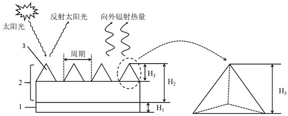
[0024] This embodiment provides a passive radiation cooling composite material film, its structure is as follows figure 1 shown. In this embodiment, the two-dimensional pyramid optical microstructure unit 3 is first prepared on a single crystal silicon substrate by chemical vapor deposition and ion etching techniques known in the art, and then obtained by nanoimprinting technology known in the art. Infrared light-emitting layer of methylsiloxane 2 . The optical microstructure unit 3 on the infrared light-emitting layer 2 is a two-dimensional pyramid optical microstructure unit 3. By adjusting the preparation process parameters, the period of the two-dimensional pyramid optical microstructure unit 3 is 8 μm, polydimethylsiloxane The thickness (H2) of the infrared light emitting layer 2 is 15 μm, the depth of the pyramid grooves (H3) is 5 μm, and the duty ratio of the pyramid optical microstructure unit 3 is 0.9. Then, a layer of planar metal reflector 1 with a thickness (H1) ...
Embodiment approach 2
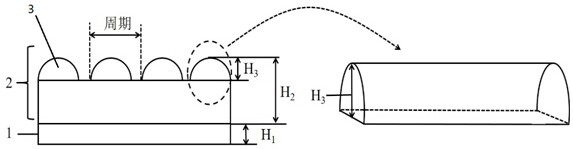
[0026] This embodiment provides a passive radiation cooling composite material film, its structure is as follows image 3 shown. In this embodiment, firstly, the one-dimensional microcylindrical lens optical microstructure unit 3 is prepared on the photoresist by using the photolithography technology and hot melt technology known in the art, and then the nanoimprinting technology known in the art is used to obtain the The infrared light emitting layer 2 of methyl siloxane, at this time, the one-dimensional microcylindrical lens optical microstructure unit 3 provided on the upper surface of the infrared light emitting layer 2 is obtained by copying and transferring from the photoresist. By adjusting the preparation process parameters, the period of the optical microstructure unit 3 of the one-dimensional microcylindrical lens is 3 μm, the thickness (H2) of the infrared light emitting layer 2 of polydimethylsiloxane is 4.5 μm, and the groove depth of the microcylindrical lens ( ...
Embodiment approach 3
[0028] This embodiment provides a passive radiation cooling composite material film, its structure is as follows Figure 5 shown. In this embodiment, firstly, the two-dimensional rectangular columnar optical microstructure unit 3 is prepared on the surface of the photoresist by using the double-beam interference lithography technique known in the art. Then, the two-dimensional cuboid column optical microstructure unit 3 on the surface of the photoresist is replicated and transferred to polydimethylsiloxane by soft nanoimprint lithography technology, thereby preparing the infrared light emitting layer 2 . By adjusting the preparation process parameters, the period of the two-dimensional cuboid column optical microstructure unit 3 is 3 μm, the thickness (H2) of the infrared light emitting layer 2 is 13 μm, and the depth of the cuboid column groove (H3) is 8 μm. The cuboid column optical microstructure unit 3 has a duty cycle of 0.7. Finally, a layer of planar metal reflector / 1...
PUM
| Property | Measurement | Unit |
|---|---|---|
| thickness | aaaaa | aaaaa |
| thickness | aaaaa | aaaaa |
Abstract
Description
Claims
Application Information
 - R&D
- Intellectual Property
- Life Sciences
- Materials
- Tech Scout
- Unparalleled Data Quality
- Higher Quality Content
- 60% Fewer Hallucinations
Browse by: Latest US Patents, China's latest patents, Technical Efficacy Thesaurus, Application Domain, Technology Topic, Popular Technical Reports.
© 2025 PatSnap. All rights reserved.Legal|Privacy policy|Modern Slavery Act Transparency Statement|Sitemap|About US| Contact US: help@patsnap.com