
Cutter wear state real-time monitoring method

A technology for real-time monitoring and tool wear, applied in manufacturing tools, time registers, measuring/indicating equipment, etc. Problems such as the inability to grasp the overall situation

Active Publication Date: 2021-03-02
GUIZHOU UNIV
View PDF6 Cites 6 Cited by
  • Summary
  • Abstract
  • Description
  • Claims
  • Application Information

AI Technical Summary

Problems solved by technology

The above methods all use deep learning to extract features adaptively, but they do not take into account the degree of correlation between time series signals, and the convolutional neural network used relies too much on high-dimensional feature extraction, and the number of convolutional layers is too large. Gradient dispersion is more likely to occur, and the number of convolutional layers is too small to grasp the overall situation, resulting in poor recognition accuracy and generalization performance of real-time monitoring of the network model

Method used


Image

  • Cutter wear state real-time monitoring method
  • Cutter wear state real-time monitoring method
  • Cutter wear state real-time monitoring method

Examples


Embodiment

[0098] 1 Experimental design

[0099] (1) Status monitoring

[0100] In the experiment of the present invention, a high-precision numerical control vertical milling machine (model: VM600) is used for milling workpieces. No coolant is added during the milling process. The milling workpieces are mold steel (S136H), and the milling cutters use ultra-fine particle tungsten carbide four-edged blades. Milling cutter with TiAIN coating on the cutting edge surface. Table 1 shows the cutting parameters of the milling experiment.

[0101] Table 1 Cutting parameters of milling experiments

[0102]

[0103] In the experiment, three acceleration sensors (model: INV9822) were magnetically adsorbed on the machine tool fixture in the x, y, and z directions to collect the original vibration signals generated during tool processing in real time; A high-precision digital acquisition instrument (model: INV3018CT) processes real-time signals and transmits them to the computer. The sampling ...


PUM


Abstract

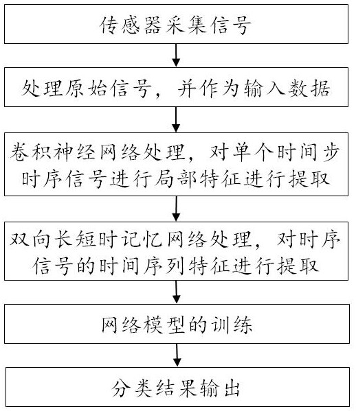
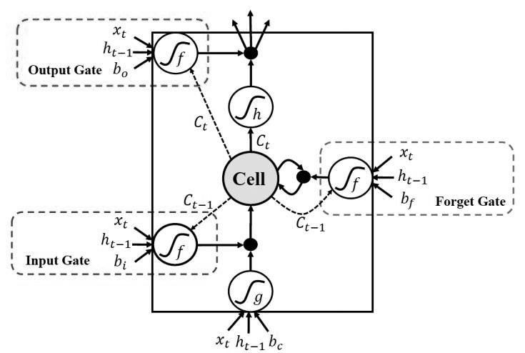
The invention discloses a cutter wear state real-time monitoring method, which comprises the following steps: acquiring an original vibration signal in real time by using an acceleration sensor, and continuously sampling and cutting the original vibration signal into a time sequence signal consisting of 2000 sampling points (2000, 3); taking the time sequence signal with the size of (2000, 3) as input data, inputting the input data into a one-dimensional convolutional neural network (CNN) for neighborhood filtering, performing calculation by using a sliding window, and finally obtaining a high-dimensional feature of a single time step time sequence signal; processing high-dimensional features generated by continuous time step time sequence signals by adopting an improved BiLSTM (Bipolar Long Short Term Memory) network; introducing an Attention mechanism to calculate importance distribution of continuous time step time sequence signal features, and generating a time sequence signal feature model containing attention probability distribution; and training the network model to obtain a wear classification result. The method has the characteristic of improving the identification precision and generalization performance of real-time monitoring of the network model.

Description

technical field [0001] The invention belongs to the field of manufacturing process monitoring, in particular to a method for real-time monitoring of tool wear status. Background technique [0002] In the machining process, cutting is the most important processing method for part forming. The wear state of the tool will directly affect the machining accuracy, surface quality and production efficiency of the part. Therefore, tool condition monitoring (Tool Condition Monitoring, TCM) technology is very important for ensuring It is of great significance to improve the quality and realize continuous automatic processing. At present, the tool condition monitoring method mainly adopts the indirect measurement method. This method can collect signals in real time through sensors during the tool cutting process. After data processing and feature extraction, the machine learning (Machine Learning, ML) model is used to monitor the tool wear. [0003] In the prior art, Zhang Cunji et al...

Claims


Application Information

Patent Timeline
IPC IPC(8): G07C3/00G06K9/62G06K9/00B23Q17/09
CPCG07C3/005B23Q17/0957G06F2218/08G06F2218/12G06F18/24G06F18/214Y02P90/02
Inventor 陈启鹏袁庆霓谢庆生黄海松李宜汀
Owner GUIZHOU UNIV
Learn More