A Broadband High Frequency Faraday Isolator
An isolator and high-frequency technology, applied in the field of broadband high-frequency Faraday isolators, can solve problems such as low isolation, difficulty in meeting device bandwidth, isolation and application frequency requirements, narrow bandwidth of isolators, etc., and achieve high application frequency Effect
- Summary
- Abstract
- Description
- Claims
- Application Information
AI Technical Summary
Problems solved by technology
Method used
Image
Examples
Embodiment 1
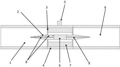
[0025] Embodiment 1: see figure 1 , a broadband high-frequency Faraday isolator, including a cavity and a permanent magnet 5, the cavity is composed of a rectangular waveguide 1, a circular waveguide 4 and a twisted waveguide 9 arranged coaxially in sequence, wherein the rectangular waveguide 1 is the input end, and the twisted waveguide The waveguide 9 is an output end; the twisted waveguide 9 is a 45° twisted waveguide, and its two ends are relatively rotated by 45°;
[0026] The circular waveguide 4 adopts an over-molded design, its size is larger than that of the standard circular waveguide at the operating frequency, and the inner wall is covered with an absorber 7, which is used to absorb higher-order modes;
[0027] A ferrite 6 is coaxially arranged in the circular waveguide 4, and matching ceramics 2 are coaxially provided at both ends of the ferrite 6, and the matching ceramics 2 are cylindrical and protrude from both ends of the circular waveguide 4 respectively. , ...
Embodiment 2
[0035] Embodiment 2: This embodiment is further improved on the basis of Embodiment 1, wherein, the circular waveguide 4 is provided with a supporting body 3 supporting a ferrite 6 and a matching ceramic 2, and the supporting body 3 is located in a circular The rings at both ends of the waveguide 4, the two ends of the matching ceramic 2 pass through the middle of the support body 3 and are supported and positioned by the support body 3. The support body 3 is made of organic glass or resin material. The absorber 7 has a loss tangent of magnetic loss and electric loss greater than 0.1 in the application frequency band, and the thickness of the absorber 7 is 0.1-0.3mm. The surfaces of the circular waveguide 4, the rectangular waveguide 1 and the twisted waveguide 9 are gold-plated.
Embodiment 3
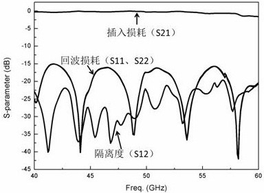
[0036] Embodiment 3: On the basis of the structure of Embodiment 1 and 2, we provide a specific embodiment, corresponding Figure 2-Figure 3 , the application frequency band of the Faraday isolator in this embodiment is 40-60 GHz, wherein the ferrite 6 is a ferrite material with a saturation magnetization of 5200 Gs and a ferromagnetic resonance linewidth of 90 Oe. Insertion loss, isolation, return loss and standing wave of the Faraday isolator of this embodiment are such as figure 2 , image 3 shown. It can be seen from the figure that the working bandwidth of the product in this embodiment is full, the transmission loss is less than 1.5dB, the isolation is greater than 22 dB, and the standing wave ratio is less than 1.45.
[0037] Table 1 shows the performance comparison between Embodiment 3 and the traditional waveguide isolator. The frequency used by the traditional stripline and microstrip isolators is relatively low, and the comparison is not included here. As shown ...
PUM
| Property | Measurement | Unit |
|---|---|---|
| thickness | aaaaa | aaaaa |
| isolation | aaaaa | aaaaa |
| isolation | aaaaa | aaaaa |
Abstract
Description
Claims
Application Information
 - Generate Ideas
- Intellectual Property
- Life Sciences
- Materials
- Tech Scout
- Unparalleled Data Quality
- Higher Quality Content
- 60% Fewer Hallucinations
Browse by: Latest US Patents, China's latest patents, Technical Efficacy Thesaurus, Application Domain, Technology Topic, Popular Technical Reports.
© 2025 PatSnap. All rights reserved.Legal|Privacy policy|Modern Slavery Act Transparency Statement|Sitemap|About US| Contact US: help@patsnap.com


