Centrifugal enrichment micro-fluidic chip for low-concentration liquid sample
A microfluidic chip and liquid sample technology, applied in the field of microfluidics, can solve the problems of small sample volume, low centrifugation efficiency, and low microbial concentration, and achieve the effect of simple operation, difficult diffusion and movement, and high efficiency
- Summary
- Abstract
- Description
- Claims
- Application Information
AI Technical Summary
Problems solved by technology
Method used
Image

Examples
Embodiment 1
[0040] Embodiment 1 Preparation of microfluidic chip:
[0041] ①Using the SU-8 photolithography method to make a microfluidic chip template.
[0042] ② Add a certain volume of SU-8 photoresist dropwise at the position of the chip sample storage cavity, and apply ultraviolet light to cure it to form an expanded and raised sample storage cavity support.
[0043] ③ Pour PDMS onto the microfluidic chip template, and cure at 70 degrees Celsius for 2 hours.
[0044] ④ Remove the PDMS layer from the template and cut it, and bond it with the glass slide through an oxygen plasma cleaning machine to complete the preparation of the microfluidic chip.
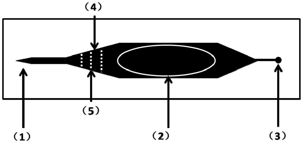
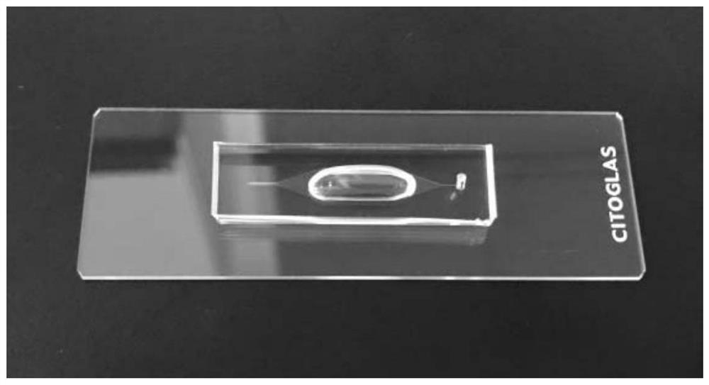
[0045] figure 1 and figure 2 The design schematic diagram and physical map of the fabricated microfluidic chip are respectively.
[0046] The enrichment microchannel 1 , the sample storage chamber 2 and the through hole 3 form a connected structure, wherein the enrichment microchannel 1 communicates with the sample storage chamber 2 t...
Embodiment 2
[0047] Example 2 sample centrifugation enrichment:
[0048] Using the microfluidic chip made in Example 1 to carry out centrifugal enrichment of samples, the specific steps are:
[0049] ① Puncture the liquid sample into the sample storage chamber through a syringe;
[0050] ②The microfluidic chip is placed in a centrifuge, the tip of the enrichment microchannel is far away from the center of the centrifuge, and the through hole is close to the center of the circle;
[0051] ③ According to the difference in density between the centrifuged product and the liquid, select an appropriate centrifugation speed for 10 to 30 minutes, so that the centrifuged product is enriched and fixed at the tip of the enrichment channel triangle.
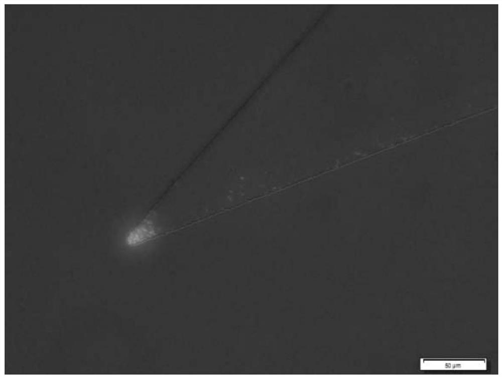
[0052] Such as image 3 Shown is the image of the sample on the enrichment chip observed on the microscope, the centrifuged product is enriched and fixed at the tip of the enrichment channel triangle
Embodiment 3
[0053] Microbiological detection and microbial drug resistance evaluation of embodiment 3 clinical urine sample:
[0054] ①Take 100 microliters of urine samples and mix them with 1 milliliter of 2X broth medium, and add 32 microliters of 1 mg / mL ampicillin solution. The following steps are the same as those in Example 2 for centrifugal enrichment.
[0055] ② Observe the chip under a microscope to determine whether the sample is infected with bacterial microorganisms.
[0056] ③ Place the centrifuged chip in a 37°C incubator for static culture, observe the growth and replication of bacteria in the antibiotic culture environment every half hour, and evaluate antibiotic resistance, such as Figure 4 is the image observed every half hour, Figure 4 A, 4B, 4C, 4D are respectively the bacterial growth observed in 0 hour, 0.5 hour, 1 hour, and 1.5 hour.
PUM
 Abstract
Description
Claims
Application Information
 - R&D
- Intellectual Property
- Life Sciences
- Materials
- Tech Scout
- Unparalleled Data Quality
- Higher Quality Content
- 60% Fewer Hallucinations
Browse by: Latest US Patents, China's latest patents, Technical Efficacy Thesaurus, Application Domain, Technology Topic, Popular Technical Reports.
© 2025 PatSnap. All rights reserved.Legal|Privacy policy|Modern Slavery Act Transparency Statement|Sitemap|About US| Contact US: help@patsnap.com