
Peaking capacitor

A technology of capacitors and capacitor dielectrics, applied in capacitors, laminated capacitors, fixed capacitors, etc., can solve the problems of difficult assembly and large volume, and achieve the effects of saving capacitor volume, solving electric field distortion, and small internal inductance

Inactive Publication Date: 2020-12-11
苏州泰思特电子科技有限公司
View PDF4 Cites 0 Cited by
  • Summary
  • Abstract
  • Description
  • Claims
  • Application Information

AI Technical Summary

Problems solved by technology

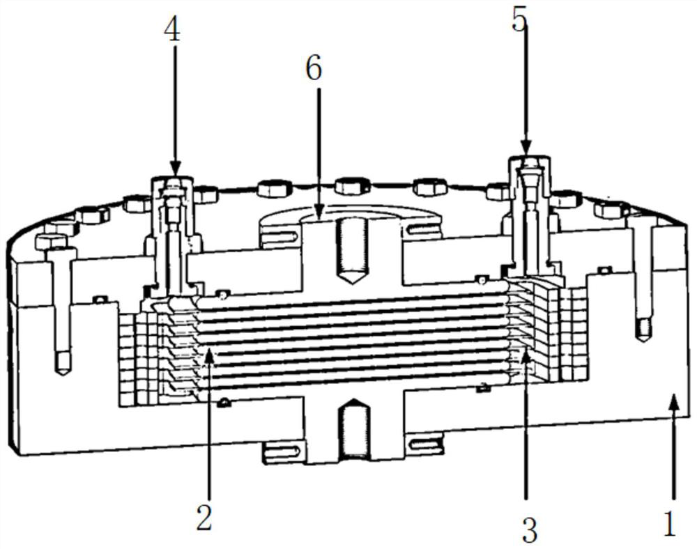
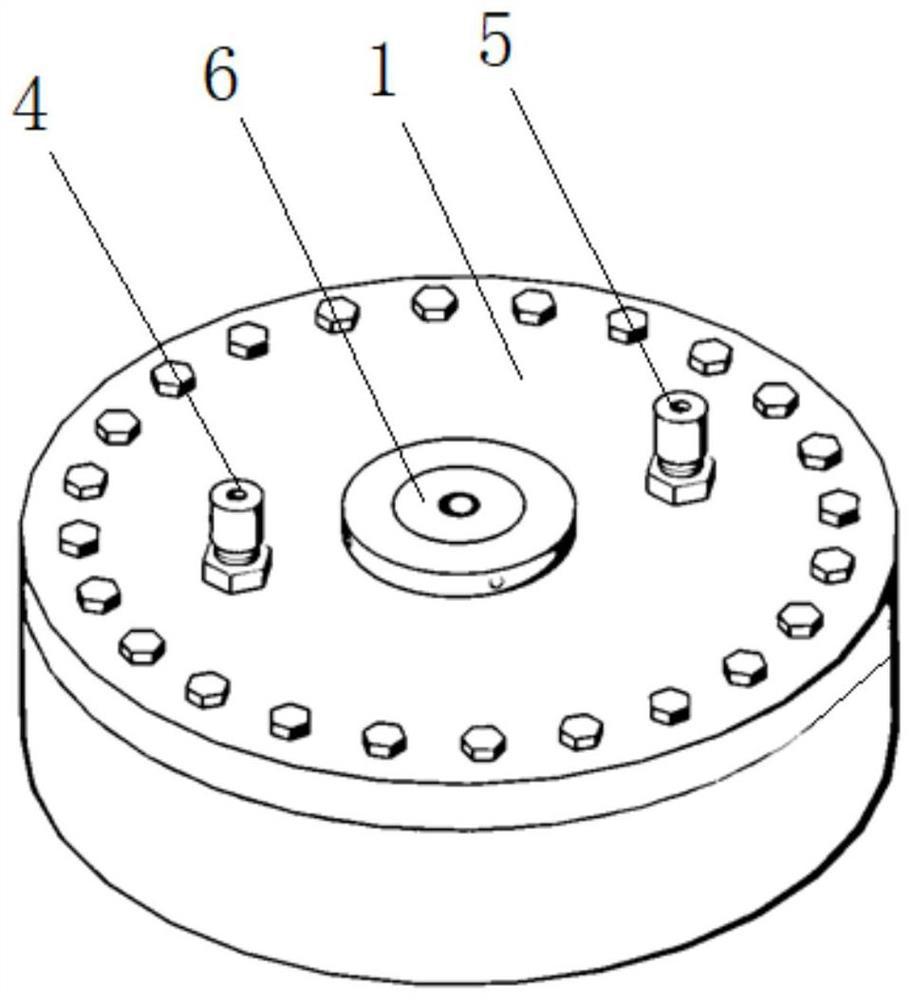
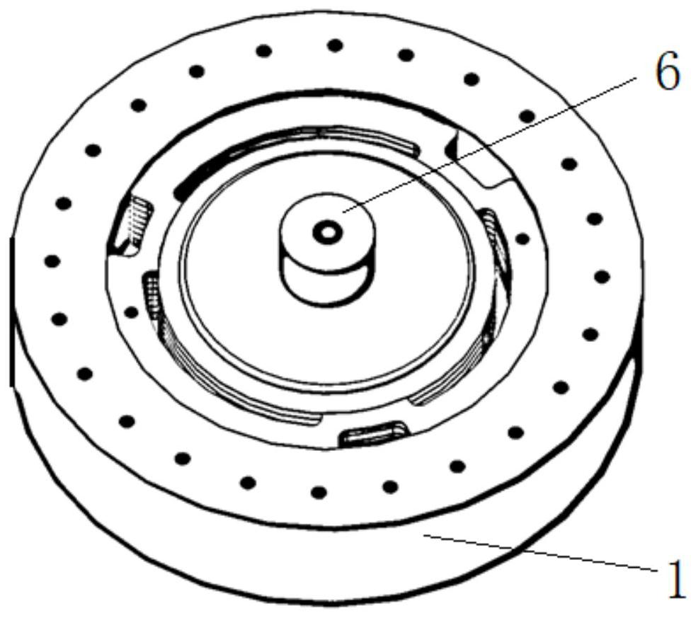
[0006] The technical problem to be solved by the present invention is: in order to solve the shortcomings of the transmission line peaking capacitor in the prior art, such as excessive volume, difficult processing and assembly, etc., thereby providing a peaking capacitor with small size, easy processing, and improved maximum operating voltage. capacitor

Method used


Image

  • Peaking capacitor
  • Peaking capacitor
  • Peaking capacitor

Examples


Embodiment Construction

[0025] It should be noted that, in the case of no conflict, the embodiments in the present application and the features in the embodiments can be combined with each other.

[0026] In the description of the present application, it should be understood that the terms "center", "longitudinal", "transverse", "upper", "lower", "front", "rear", "left", "right", " The orientation or positional relationship indicated by "vertical", "horizontal", "top", "bottom", "inner", "outer", etc. is based on the orientation or positional relationship shown in the drawings, and is only for the convenience of describing the present application and Simplified descriptions do not indicate or imply that the device or element referred to must have a specific orientation, be constructed and operate in a specific orientation, and thus should not be construed as limiting the scope of protection of the present application. In addition, the terms "first", "second", etc. are used for descriptive purposes on...


PUM

PropertyMeasurementUnit
Dielectric strengthaaaaaaaaaa

Abstract

The invention relates to a peaking capacitor which comprises a capacitor core, an insulating shell and a high-pressure insulating gas circuit. The interior of the insulating shell is sealed to form asealed cavity, the capacitor core is fixed in the sealed cavity, the high-pressure insulating gas circuit is communicated with the sealed cavity and inputs inert gas, and the capacitor core comprisesa plurality of capacitors which are connected in series. The capacitor has the beneficial effects that the biaxially oriented stretched single-sided rough polypropylene film is used as a dielectric material, so that the dielectric strength is extremely high; through a multi-capacitor series connection technology, a plurality of intermediate electrodes are added, so that the distance between singlecapacitor plates is greatly shortened, and the problem of electric field distortion between the capacitor inner plates is solved; the hidden danger of internal sliding flashover is effectively eliminated by increasing the diameter of the medium and inflating the inside; the electrode is of a laminated structure, the current is propagated along the axial direction of the capacitor, and the internal inductance is small; based on the parallel plate principle, the diameters of the pole plates are consistent, so that only a small area is needed, and the volume of the capacitor is saved.

Description

technical field [0001] The application belongs to the field of pulse power devices, and in particular relates to a peaking capacitor. Background technique [0002] Pulse power technology is a device that compresses electric energy in space (energy storage devices such as capacitors or inductors) and time (large-capacity fast switching), and releases huge power in an instant. Various particle accelerators, various ray generators, particle generators, electromagnetic pulse simulators, high-power microwave simulators, and lightning effect simulators all belong to this type of device, which is the frontier field of scientific and technological research. [0003] The rise time (pulse leading edge) of the pulse generated by the pulse power device is proportional to the inductance of the loop and inversely proportional to the resistance of the load. When the load of the device is certain, in order to obtain a fast rise time pulse, the inductance of the loop must be strictly contro...

Claims


Application Information

Patent Timeline
IPC IPC(8): H01G4/14H01G4/33H01G4/38H01G4/005H01G4/002
CPCH01G4/002H01G4/005H01G4/14H01G4/33H01G4/385
Inventor 刘顺坤黄学军刘煜
Owner 苏州泰思特电子科技有限公司
Learn More