Micro-miniature igniter based on micro-heater and structural energetic material and preparation of micro-miniature igniter
A technology of micro-heater and igniter, which is applied in the direction of weapon accessories, offensive equipment, blasting barrels, etc.
- Summary
- Abstract
- Description
- Claims
- Application Information
AI Technical Summary
Problems solved by technology
Method used
Image
Examples
preparation example Construction
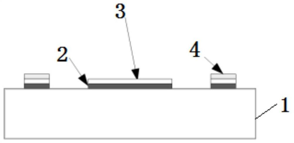
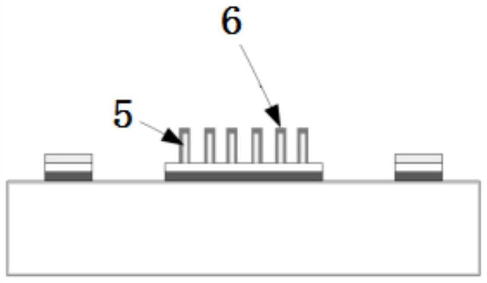
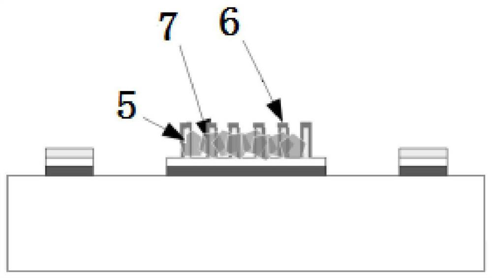
[0074] The invention also relates to a preparation method of a micro-miniature igniter based on a micro-heater and a waterproof structure energy-containing material embedded with an explosive thermite array. The method comprises the following steps: step 1: preparing a micro heater; step 2: preparing a structure thermite array; step 3: complying with explosives in situ; and step 4: encapsulating hydrophobic materials.
[0075] Figure 1-Figure 4 Shown are the steps of a preferred preparation method of the present invention. In step 1, materials are sequentially deposited on the substrate by photolithography and physical deposition processes to prepare micro heaters. The material composition of the micro-heater is an adhesion layer 2 , a heater layer 3 and a bonding layer 4 sequentially from the base material 1 . The adhesion layer 2 can be selected according to the materials of the substrate 1 and the heater layer 3, such as but not limited to titanium (Ti), chromium (Cr), t...
Embodiment 1
[0085] A micro-heater with a specific shape is prepared on the surface of a silicon wafer by photolithography. The adhesion layer Cr, the heater layer Pt, and the bonding layer Au are sequentially deposited outside the area covered by the photoresist mask layer by thermal evaporation, and then the Au outside the bonding area is removed by photolithography to expose the heater. Area Pt.
[0086] Outside the heater region was protected by a photoresist mask layer, 100 nm CuO was deposited by magnetron sputtering, followed by 1.5 µm Cu by electron beam evaporation. Thermal oxidation at 400 °C for 12 h in a furnace filled with static air allowed Cu to grow into CuO nanowire arrays. Al was then deposited outside the CuO nanowires with a nominal thickness of 1 μm by electron-beam evaporation in order to obtain a core-shell CuO / Al nanorod array.
[0087] Next, 43.8 mg of CL20 was added to 0.5 ml of acetone, ultrasonicated for 5 minutes, and 10 microliters of the resulting solution ...
Embodiment 2
[0089] A micro-heater with a specific shape is prepared on the surface of a silicon wafer by photolithography. The adhesion layer Cr, the heater layer Pt, and the bonding layer Au are sequentially deposited outside the area covered by the photoresist mask layer by thermal evaporation, and then the Au outside the bonding area is removed by photolithography to expose the heater. Area Pt.
[0090] The area outside the heater area was protected by a photoresist mask layer, and Mg was deposited by thermal evaporation at a grazing angle of 84 degrees to obtain Mg nanorod arrays. Copper oxide with a nominal thickness of 200 nm was then deposited outside the Mg nanorods by magnetron sputtering to obtain a core-shell Mg / CuO nanorod array.
[0091] Next, 11 mg of CL20 was added to 0.1 ml of acetone, ultrasonicated for 5 minutes, and 10 microliters of the resulting solution was added dropwise to the CuO / Al nanostructure array. After being placed in the fume hood for 30 minutes, deposit...
PUM
 Abstract
Description
Claims
Application Information
 - R&D Engineer
- R&D Manager
- IP Professional
- Industry Leading Data Capabilities
- Powerful AI technology
- Patent DNA Extraction
Browse by: Latest US Patents, China's latest patents, Technical Efficacy Thesaurus, Application Domain, Technology Topic, Popular Technical Reports.
© 2024 PatSnap. All rights reserved.Legal|Privacy policy|Modern Slavery Act Transparency Statement|Sitemap|About US| Contact US: help@patsnap.com


