Grout feeding device

A technology of cement slurry and discharge device, which is applied in the field of cement slurry mixing, which can solve the problems of physical damage to workers, reduce manpower intensity, and slow feeding speed, and achieve the effects of protecting health, wide application range, and reducing difficulty

Pending Publication Date: 2020-10-30
申旭正
View PDF2 Cites 0 Cited by
  • Summary
  • Abstract
  • Description
  • Claims
  • Application Information

AI Technical Summary

Problems solved by technology

This method is labor-intensive. During the process of pouring cement, there is more cement dust. Performing high-intensity labor in this dusty environment also brings great damage to the health of the workers; the large pieces contained in the cement Impurities are directly poured into the mixing mechanism without filtering, which is easy to cause damage to the blades in the mixing mechanism
[0003] The Chinese utility model patent with the publication number CN209097776U discloses a cement feeding device, which includes a feeding hopper, an operating arm, a tipping bucket hydraulic cylinder, a linear reciprocating mechanism, a bag grabbing mechanism and a bag breaking mechanism, and the front end of the feeding hopper is hollowed out. The front end of the operating arm is hinged to the bottom of the rear end surface of the upper hopper, and the front end of the dump bucket hydraulic cylinder is hinged to the middle or upper part of the rear end surface of the upper hopper; the linear reciprocating moving part of the linear reciprocating mechanism passes through the rear end surface of the upper hopper; the grab bag The mechanism is set on the front end of the linear reciprocating movement part of the linear reciprocating mechanism, and the bag breaking mechanism is set on the upper hopper. This utility model can replace manpower to realize the grasping, cutting and pouring of bagged cement into the concrete mixer. In the mechanism, the manpower intensity is reduced, and there is no need to manually cut the bag and pour the cement, and the laborers can stay away from the place where the bag is cut and the cement is poured, which can effectively reduce the damage to the laborers caused by the cement dust caused by cutting the bag and pouring the cement. However, the material is still fed in the form of cement powder, and the feeding speed is slow. Although the laborers are far away from places with large dust, the dust still exists, and the problem of large dust has not been fundamentally solved.
[0004] The Chinese utility model patent with the publication number CN207140067U discloses an automatic cement pulping machine, including a bracket, a load cell connected to the bracket, a pulping bucket, a pulping shaft located in the pulping bucket, an impeller and a plurality of drainage plate, the reducer connected to the pulping shaft through the pulping transmission assembly, and the controller electrically connected to the reducer, water feeder and cement feeding machine; among them, the load cell is used to weigh the pulping barrel and its internal slurry , and transmit the weight signal to the controller; the impeller adopts a three-layer staggered structure, and the stirring is more sufficient; the drainage plate is fixed on the barrel wall obliquely, which can prevent the slurry from overflowing from the pulping barrel, and the pulping quality and efficiency are high, but The feeding method of the feeding machine is to add gradually, and stir while adding. The stirring time is long and the pulping efficiency is low.

Method used


Image

  • Grout feeding device
  • Grout feeding device
  • Grout feeding device

Examples


Embodiment 1

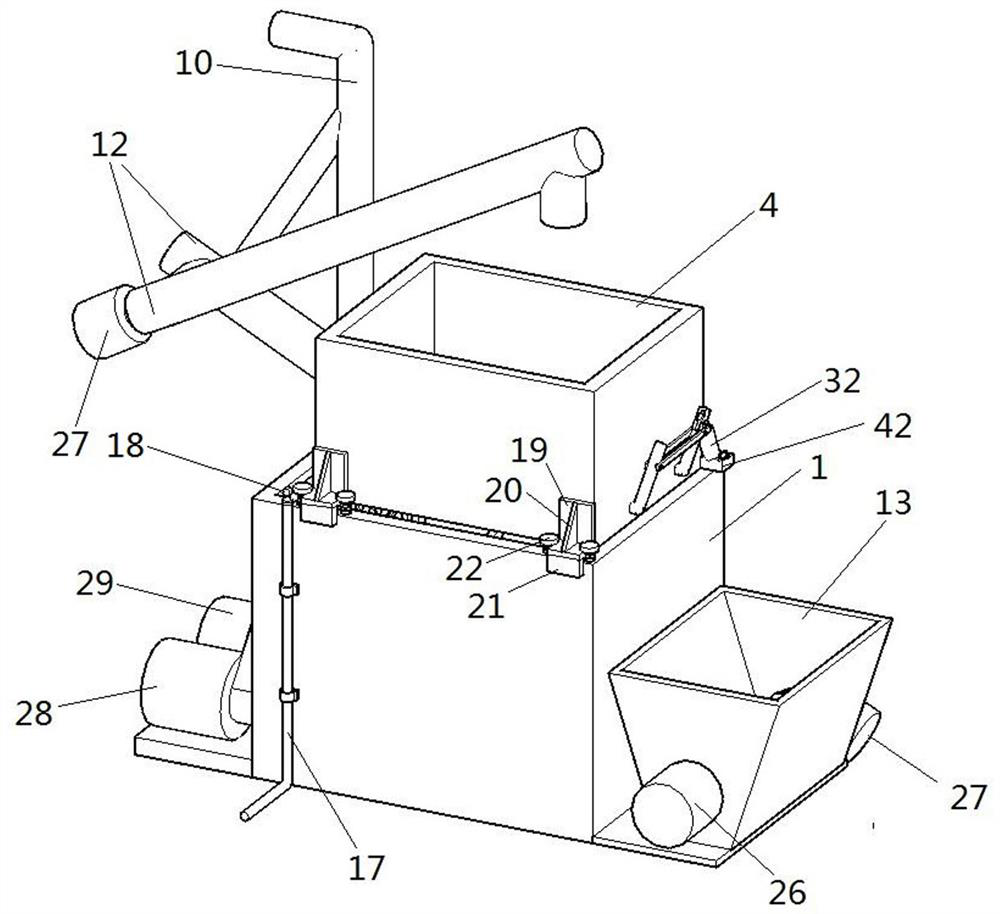
[0044] like Figure 1-8 Shown is the first embodiment of the present invention, a cement slurry feeding device, including a feeding device, a measuring device, a stirring device and a discharging device, and the stirring device is a steel stirring hopper 1 with an open upper end. The structure is shown in Figure 4. It is welded by the front plate, the rear plate, the bottom plate and the left and right side plates. The center of the right plate of the mixing bucket 1 is punched by a punching machine, and the center of the left plate of the mixing bucket 1 is punched by a punching machine. For the blind hole corresponding to the through hole, one end of the steel shaft one 2 is inserted into the blind hole after passing through the through hole. A plurality of stirring rods 3 are uniformly welded at an equal angle on the rotating shaft one 2, and the stirring rods 3 are perpendicular to the rotating shaft one 2.

[0045] The mixing hopper 1 is provided with a measuring device....

Embodiment 3

[0053] like Figure 10 Shown is the third embodiment of the present invention. The difference between this embodiment and the first embodiment is that the end of each stirring rod 3 is welded with a cuboid plate-shaped stirring blade 23 . Stirring blades are arranged at the end of the stirring rod to shorten the stirring time and make the stirring more uniform.

Embodiment 4

[0055] like Figure 11 and Figure 12 Shown is the fourth embodiment of the present invention. The difference between the present embodiment and the first embodiment is that the discharge pipe 10 is composed of an upper pipe 34 and a lower pipe 35, and the bottom end of the lower pipe 35 is vertically installed on the tee joint 15 Inside, the upper flange 36 is press-fitted on the bottom end of the upper tube 34, the lugs in the shape of a cuboid are welded on both sides of the upper flange 36, the top of the lower tube 35 is pressed into the lower flange 37, and the lugs in the shape of a cuboid are welded on both sides of the lower flange 37. Ear 2, the upper and lower correspondence between lug 1 and lug 2, the lug 1 and lug 2 on the same side are hinged through hinges, and the lug 1 and lug 2 on the other side are respectively hinged The hole machine drills the corresponding through holes up and down, inserts the bolts in the through holes, and nuts are arranged at the ot...


PUM


Abstract

The invention discloses a grout feeding device. The grout feeding device comprises a stirring device, a material weighing device and a discharging device. The stirring device comprises a stirring hopper with an opening in the upper end. A first rotating shaft is connected with the interior of the stirring hopper in a rotating mode, and stirring rods are evenly arranged on the first rotating shaft.The material weighing device comprises a material weighing hopper with an opening in the upper end. The material weighing hopper is located on the top of the stirring hopper, and a pressure sensor isarranged between the material weighing hopper and the stirring hopper. Two rotating plates are arranged on the lower portion of the interior of the material weighing hopper, and a driving assembly which drives the two rotating plates to simultaneously rotate in the same direction is arranged on the material weighing hopper. The discharging device comprises a delivery pump. A feeding inlet of thedelivery pump communicates with the stirring hopper through a first connecting pipe, and a discharging outlet of the delivery pump is connected with a first discharging pipe. The grout feeding devicefeeds materials into a stirring mechanism in a grout mode, and is high in feeding efficiency and little in raising dust.

Description

technical field [0001] The invention relates to the field of cement slurry mixing, in particular to a cement slurry feeding device. Background technique [0002] With the promotion of mechanization, the existing concrete mixing is mainly carried out by using a concrete mixer, and the concrete for construction is obtained by putting cement, silt, stone, etc. into the mixing mechanism of the concrete mixer. The cement currently used is mainly bagged cement. Putting the bagged cement into the mixing mechanism of the concrete mixer is mainly realized by manpower. The bagged cement is transferred to the feeding port of the mixing mechanism through the elevator, and then the cement bag is opened. , and rely on manpower to pour the cement into the mixing mechanism. This method is labor-intensive. In the process of pouring cement, there is a lot of cement dust. High-intensity labor in such a dusty environment will also cause great damage to the health of the workers; Impurities ar...

Claims


Application Information

Patent Timeline
IPC IPC(8): B28C5/14B28C7/04B28C7/08
CPCB28C5/14B28C7/044B28C7/08
Inventor 申旭正
Owner 申旭正
Why Eureka
Try Eureka