Extended multilevel boost inverter topology and modulation method

A step-up inverter and multi-level technology, which is applied to electrical components, AC power input conversion to DC power output, output power conversion devices, etc., can solve the problem that the level gain cannot be changed

Active Publication Date: 2021-07-06
ZHENGZHOU UNIV
View PDF4 Cites 0 Cited by
  • Summary
  • Abstract
  • Description
  • Claims
  • Application Information

AI Technical Summary

Problems solved by technology

However, no matter how many switched capacitor sub-modules are expanded, the extended switched capacitor sub-module can only improve the quality of the output power of the inverter topology, but cannot change the level gain; the gain of the output level of the switched capacitor N-level inverter topology remains consistent at 2V dc , in order to obtain a higher AC output voltage, it is usually necessary to use a front-end DC-DC boost structure

Method used


Image

  • Extended multilevel boost inverter topology and modulation method
  • Extended multilevel boost inverter topology and modulation method
  • Extended multilevel boost inverter topology and modulation method

Examples


Embodiment 1

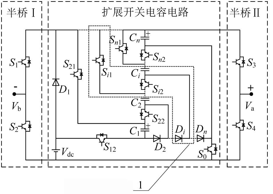
[0030] as attached figure 1 As shown, an extended multi-level boost inverter topology, which includes half-bridge I, half-bridge II and extended switched capacitor circuit; wherein, the midpoint of the half-bridge I and the midpoint of the half-bridge II as The AC output terminal of the extended switched capacitor multi-level boost inverter topology;

[0031] The half-bridge I includes a switching tube S 1 with switch S 2 , the half-bridge II includes a switch S 3 with switch S 4; The extended switched capacitor circuit includes a switched capacitor basic module and at least one level of switched capacitor sub-module 1; the switched capacitor basic module includes a switch tube S 12 , switch tube S 0 , Diode D 1 and electrolytic capacitor C 1 , the switched capacitor sub-module 1 includes a switch tube S i1 , switch tube S i2 , Diode D i and electrolytic capacitor C i , (i=2,3,...,n);

[0032] Among them, the switching tube S of the half-bridge I 1 collector of th...

Embodiment 2

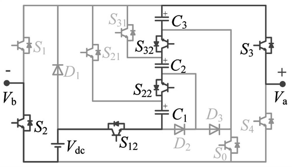
[0048] This embodiment provides a specific implementation manner of extending three switched capacitor sub-modules, as shown in Figure 2(a)-(i) of the accompanying drawings.

[0049] When a 3-level switched capacitor sub-module is configured, the extended multi-level boost inverter topology works in 9 modes:

[0050] Mode 1, as shown in Figure 2(a): switch tube S 2 , switch tube S 3 , switch tube S 12 , switch tube S 22 and switch tube S 32 is turned on, the rest of the switches are turned off, and the diode D 1 , Diode D 2 and diode D 3 Reverse bias cut-off; at this time, the electrolytic capacitor C 1 , electrolytic capacitor C 2 , electrolytic capacitor C 3 with DC input supply V dc Series discharge, inverter topology output 4V dc ;

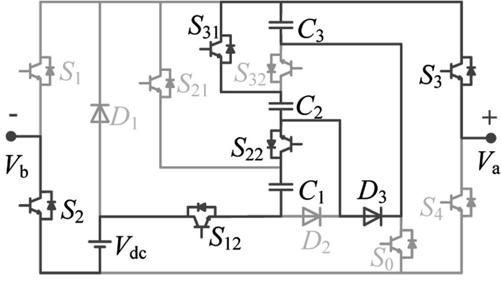
[0051] Mode 2, as shown in Figure 2(b): switch tube S 2 , switch tube S 3 , switch tube S 12 , switch tube S 22 and switch tube S 31 is turned on, the rest of the switches are turned off, and the diode D 1 and diode D 2 Reve...

Embodiment 3

[0070] An extended multi-level boost inverter system, including a controller and an inverter topology, the inverter topology is the above-mentioned extended multi-level boost inverter topology; the controller includes DSP and FPGA and peripheral circuits, the The controller is communicated with the inverter topology, so as to realize the adjustment of the working mode by adjusting the on-off of the switch tube. When the controller controls the actions of the switch tubes in the extended multi-level boost inverter topology, it executes the steps of the above-mentioned extended multi-level boost inverter topology modulation method.


PUM


Abstract

The present invention provides an extended multi-level boost inverter topology and a modulation method. The extended multi-level boost inverter topology includes half-bridge I, half-bridge II and an extended switched capacitor circuit. Controlling the series-parallel conversion between the DC input power supply and the extended switched capacitor circuit; the half bridge I and the half bridge II are used to complete the positive and negative polarity conversion of the output level of the extended switched capacitor circuit; the inverter topology The number of output levels and the boost gain can be further improved through the modular expansion of the switched capacitor unit. The inverter topology circuit with n-level switched capacitor sub-modules can output a total of 2n+3 voltage levels, and the highest level of voltage can be It reaches (n+1) times of the DC input voltage; the topology reduces the number of devices used, and the self-balancing of the capacitor voltage can be realized without complex voltage balance control, and the complementary working mechanism of the switch pair simplifies the modulation strategy.

Description

technical field [0001] The invention relates to the fields of electric energy conversion and new energy power generation, and in particular relates to an extended multilevel boost inverter topology and a modulation method. Background technique [0002] Since the multi-level inverter topology has more output levels, it can reduce the total harmonic distortion of the output waveform, thereby improving the quality of output power and reducing the size of the filter. It is widely used in new energy fields such as distributed photovoltaic power generation. . [0003] Traditional multilevel inverter topologies are mainly divided into three types: midpoint clamp type, flying capacitor type and cascaded H-bridge type. Among them, the mid-point clamp type and flying capacitor type inverter topologies have disadvantages such as complex topology and difficult balance of capacitor voltage; although the cascaded H-bridge inverter topology has the advantages of simple modular structure a...

Claims


Application Information

Patent Timeline
Patent Type & Authority Patents(China)
IPC IPC(8): H02M7/483H02M7/5387
CPCH02M7/483H02M7/53871H02M1/007H02M7/4835
Inventor 王要强王凯歌陈天锦秦明王克文梁军
Owner ZHENGZHOU UNIV
Why Eureka
Try Eureka