
Equipment fault defect diagnosis method based on improved U-Net neural network

A technology for equipment failure and defect diagnosis, which is applied in the field of equipment appearance failure and defect crack diagnosis. It can solve problems such as slow training speed, inability to achieve pixel-level positioning accuracy in complex backgrounds, and increased memory overhead.

Active Publication Date: 2020-09-04
JIANGSU YUANWANG INSTR
View PDF6 Cites 4 Cited by
  • Summary
  • Abstract
  • Description
  • Claims
  • Application Information

AI Technical Summary

Problems solved by technology

[0003] 1. CNN is mainly used for image-level classification, learning the abstract features of images; however, due to the loss of low-resolution pixel classification in the process of convolution and pooling, it is impossible to achieve pixel-level positioning in complex backgrounds precision;
[0004] 2. When the CNN model performs pixel classification on complex background images, there is a high degree of overlap between the classification blocks of adjacent pixels, which introduces a large amount of data redundancy and increases memory overhead, resulting in a very time-consuming network and slow training speed.
[0005] 3. The images output by the current semantic segmentation network are mainly grayscale images. For users, it is impossible to directly integrate the crack appearance, location and equipment for identification, which is not conducive to the user's immersive experience.
[0008] There are also diagnostic technologies based on the U-Net network model, but they are all applications of the original U-Net network model, which cannot take into account the computing performance requirements and the complexity of the image, and there are still problems in the actual application that the recognition is not accurate enough, or the computing Problems with high performance requirements

Method used


Image

  • Equipment fault defect diagnosis method based on improved U-Net neural network
  • Equipment fault defect diagnosis method based on improved U-Net neural network
  • Equipment fault defect diagnosis method based on improved U-Net neural network

Examples


Embodiment Construction

[0081] The present invention will be further described below in conjunction with accompanying drawing.

[0082] The invention is based on the improved U-Net neural network equipment failure defect diagnosis method, mainly including three major functional modules: image enhancement, 3D display based on the improved U-Net neural network model and fault location and shape. Among them, in order to solve the problem that the original appearance image of the device may not be directly used for network training due to the uncertainty of the source, the size, quantity, and image quality, the original image is adjusted by size adjustment, flipping, and angle rotation. The size, quantity, shape, etc. of the image are processed by the front-end, and the original image set is optimized by means of image enhancement, and then the optimized sample is put into the improved U-Net neural network model for training, and finally the output is the same size as the original image. Pixel-level imag...


PUM


Abstract

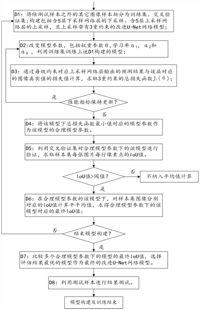
The invention discloses an equipment fault defect diagnosis method based on an improved U-Net neural network. The method comprises the following steps: constructing an improved U-Net network model which contains five down-sampling network layers and five up-sampling network layers and has triple constraints; wherein the triple constraints include three-level loss constraints on a fifth upsamplingnetwork layer located at the bottommost layer, two-level loss constraints on a fourth upsampling network layer adjacent to the fifth upsampling network layer and one-level loss constraints on a firstupsampling network layer located at the topmost layer. According to the invention, defect crack position and shape prediction and generation are carried out on an original image by using an improved U-Net neural network model; 3D display interaction is carried out through a WebGL method, the precision and correctness of equipment appearance crack pixel-level prediction are further improved, meanwhile, the picture experience feeling of man-machine interaction is remarkably improved, effective recognition and precise positioning of the equipment appearance defect crack position are facilitated,and the maintenance cost is reduced.

Description

technical field [0001] The invention relates to the technical field of equipment fault expedition diagnosis, in particular to a technology for diagnosing equipment appearance faults and defect cracks based on an improved U-Net neural network model. Background technique [0002] In recent years, with the development of computer hardware and the emergence of super-large-scale learning samples, deep learning technology represented by convolutional neural network (CNN) has shown great promise in the application of object detection and classification in the field of computer vision CV. Powerful performance. Because CNN can automatically learn and generate highly complex nonlinear features, it breaks through the limitations of traditional threshold alarms, reduces workload, shortens the inspection cycle, and reduces the false detection rate. Therefore, it is widely used in the fault diagnosis and detection of equipment. However, as the accuracy and real-time requirements of equi...

Claims


Application Information

Patent Timeline
IPC IPC(8): G06T7/00G06K9/62G06N3/04G06N3/08G01N21/88
CPCG06T7/0004G06N3/084G01N21/8851G06T2207/20081G06T2207/30108G01N2021/8883G06N3/045G06F18/241G06F18/214
Inventor 程鲲鹏戴林刘新辉吉承成
Owner JIANGSU YUANWANG INSTR
Learn More