Micro-fluidic chip for detecting survivable organisms in water body and detection method
A microfluidic chip and biological detection technology, applied in fluid controllers, chemical instruments and methods, laboratory containers, etc., can solve the problems of unsuitable detection of coliform bacteria, failure to achieve effectiveness, long detection cycle, etc. problems, to achieve efficient and reliable detection, reduce the risk of sample contamination, and low cost
- Summary
- Abstract
- Description
- Claims
- Application Information
AI Technical Summary
Problems solved by technology
Method used
Image
Examples
Embodiment 1
[0038] Embodiment 1: the preparation of chip
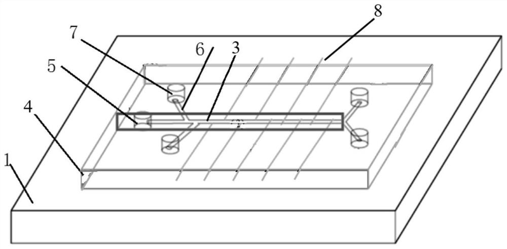
[0039] Such as figure 1 As shown, the microfluidic chip used for the detection of survivable organisms in the water body in this embodiment is fabricated by using the "single exposure" technique and the ultraviolet lithography method. After the silicon wafer is treated with a sulfuric acid hydrogen peroxide solution, washed and dried, a layer of SU-82035 negative photoresist is cast on the surface with a glue spreader at a speed of 3000rpm, and baked at 65°C for 10min and at 95°C for 4min Afterwards, after ultraviolet exposure, secondary curing, development, and nitrogen blow-drying, the patterns of each chamber and microchannel network are obtained. Then silanize to make the surface of the mold hydrophobic, polydimethylsiloxane (PDMS) prepolymer and initiator are mixed at a mass ratio of 10:1 to cover the mold, and after removing air bubbles, place it at 75°C for curing. The polymerized PDMS sheet is carefully peeled off, cut i...
Embodiment 2
[0040] Embodiment 2: the structure of the chip
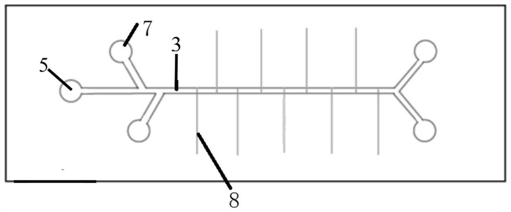
[0041] Such as figure 1 As shown, the microfluidic chip used for the detection of viable organisms in water in this embodiment includes a channel layer 4, a dielectric layer 2 and a dielectric layer bonded sequentially from top to bottom. The base layer 1; the channel layer 4 is provided with an inlet unit, a bacterial electrophoresis control unit and an outlet unit connected in sequence; the inlet unit and the outlet unit all sequentially pass through the channel layer 4 and the dielectric layer 2 .
[0042] The inlet unit includes a bacteria mixture tank 5, a buffer tank 7 and a side channel 6; the outlet unit includes two waste tanks; the bacteria electrophoresis control unit includes a main channel 3, 8 groups of metal microelectrodes and a flat plate drive electrode; the bacterial mixture tank 5 is arranged at one end of the main channel 3, and the two waste liquid tanks are arranged at the other end of the main channel 3...
Embodiment 3
[0053] Embodiment 3: dielectrophoresis technology is used for bacterial detection and separation
[0054] An electrode system is installed at the bottom of the device, which produces different driving effects on different kinds of bacteria during detection. Such as Figure 4 The bacteria are driven by the electrode on the bottom side of the sample tank, so that there is an axial mutual separation between different bacteria, that is, different bacteria are separated due to differences in physical and chemical properties, and they are concentrated in a certain area to move forward. After separation, the metal microelectrodes 8 staggered on both sides of the main channel 3 perform electrical focusing on the separated bacterial zones, so that various bacteria are concentrated in the center of each zone, which is convenient for detection. The sensing electrodes on both sides of the detection area monitor in real time, and the change of conductivity of the solution in the conductio...
PUM
| Property | Measurement | Unit |
|---|---|---|
| width | aaaaa | aaaaa |
| depth | aaaaa | aaaaa |
| diameter | aaaaa | aaaaa |
Abstract
Description
Claims
Application Information
 - R&D Engineer
- R&D Manager
- IP Professional
- Industry Leading Data Capabilities
- Powerful AI technology
- Patent DNA Extraction
Browse by: Latest US Patents, China's latest patents, Technical Efficacy Thesaurus, Application Domain, Technology Topic, Popular Technical Reports.
© 2024 PatSnap. All rights reserved.Legal|Privacy policy|Modern Slavery Act Transparency Statement|Sitemap|About US| Contact US: help@patsnap.com


