A kind of graphene heat pipe and preparation method thereof

An ene heat pipe and graphene technology, applied in the field of heat pipes, can solve the problems of reduced effective condensation area, deterioration of heat transfer performance, complex preparation process, etc., and achieve the effects of reducing energy consumption, prolonging life, and good heat transfer performance

Active Publication Date: 2021-11-02
福建永安市永清石墨烯研究院有限公司 +1
View PDF0 Cites 0 Cited by
  • Summary
  • Abstract
  • Description
  • Claims
  • Application Information

AI Technical Summary

Problems solved by technology

[0003] The existing technology has the following disadvantages: (1) The preparation process is relatively complicated, and the sintering process in the process: the production of the liquid-absorbing core needs to heat and sinter the copper pipe, and the sintering temperature is relatively high. Generally, the temperature is controlled at 900°C-1000°C, which can (2) The powder filling process in the preparation process: when the copper powder is filled, the copper powder will sinter on the plug and the copper tube, resulting in a great force to take out the plug after sintering, and sometimes it will fail because it cannot be taken out. Waste products are generated, and the waste rate reaches more than 25%; (3) Non-condensable gas is an important factor affecting the heat transfer performance of heat pipes: the working liquid and the tube core produce chemical or electrochemical reactions to produce non-condensable gas, the gas Swept by the steam to the condensing section and gather to form an air lock, thereby reducing the effective condensation area, increasing the thermal resistance, deteriorating the heat transfer performance, decreasing the heat transfer or even failing

Method used


Image

  • A kind of graphene heat pipe and preparation method thereof
  • A kind of graphene heat pipe and preparation method thereof
  • A kind of graphene heat pipe and preparation method thereof

Examples


Embodiment 1

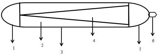
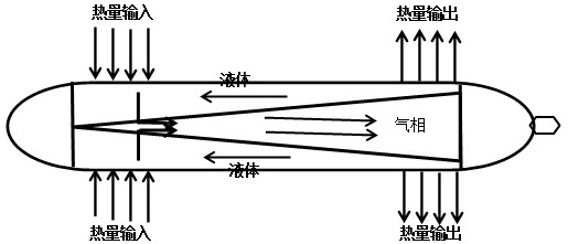
[0025] refer to figure 1 , the graphene heat pipe of the present invention includes an evaporation end cover 1 and a heat dissipation end cover 5, a tube shell 3 is arranged in the middle of the evaporation end cover 1 and a heat dissipation end cover 5, and a liquid-absorbing core 2 is arranged inside the tube shell 3 And the hollow part 4, the liquid-absorbing core 2 is composed of gradient one 201, gradient two 202, gradient three 203 and gradient four 204, the hollow part 4 is in the shape of a triangular cone, and its radius is smaller than the pipe diameter of the shell 3.

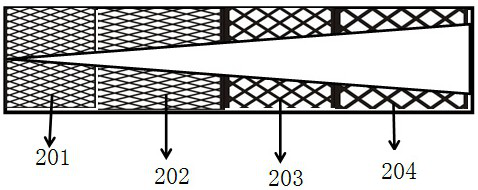
[0026] In this embodiment, the liquid-absorbing core 2 attached to the tube shell 3 is provided with variable apertures, and its specific distribution method is that the apertures increase sequentially from the evaporation end to the heat dissipation end; the four gradients are respectively: the number of apertures in gradient one 201 is 200 -300, the porosity change is 0.75-0.89, the number of pores...

Embodiment 2

[0035] refer to figure 1 , the graphene heat pipe of the present invention includes an evaporation end cover 1 and a heat dissipation end cover 5, a tube shell 3 is arranged in the middle of the evaporation end cover 1 and a heat dissipation end cover 5, and a liquid-absorbing core 2 is arranged inside the tube shell 3 And the hollow part 4, the liquid-absorbing core 2 is composed of gradient one 201, gradient two 202, gradient three 203 and gradient four 204, the hollow part 4 is in the shape of a triangular cone, and its radius is smaller than the pipe diameter of the shell 3.

[0036] In this embodiment, the liquid-absorbing core 2 attached to the tube shell 3 is provided with variable apertures, and its specific distribution method is that the apertures increase sequentially from the evaporation end to the heat dissipation end; the four gradients are respectively: gradient one 201 hole number 210 -300, the porosity change is 0.78-0.9; the number of pores in gradient two 20...

Embodiment 3

[0044] refer to figure 1 , the graphene heat pipe of the present invention includes an evaporation end cover 1 and a heat dissipation end cover 5, a tube shell 3 is arranged in the middle of the evaporation end cover 1 and a heat dissipation end cover 5, and a liquid-absorbing core 2 is arranged inside the tube shell 3 And the hollow part 4, the liquid-absorbing core 2 is composed of gradient one 201, gradient two 202, gradient three 203 and gradient four 204, the hollow part 4 is in the shape of a triangular cone, and its radius is smaller than the pipe diameter of the shell 3.

[0045] In this embodiment, the liquid-absorbing core 2 attached to the tube shell 3 is provided with variable apertures, and its specific distribution method is that the apertures increase sequentially from the evaporation end to the heat dissipation end; the four gradients are respectively: gradient one 201 hole number 210 -300, the porosity change is 0.75-0.9; the number of pores in gradient two 20...


PUM

PropertyMeasurementUnit
thicknessaaaaaaaaaa
diameteraaaaaaaaaa
radiusaaaaaaaaaa

Abstract

The invention discloses a graphene heat pipe and a preparation method thereof. In the invention, the metal tube is shrunk first, and one end is sealed to obtain a tube shell; a core rod is inserted into the tube shell, and graphene slurry is poured into the core rod and the tube shell In the cavity between them; after solidification and cooling, the mandrel is removed to obtain the shell; finally, the unclosed end of the shell with the liquid-absorbing core and the end cap with the filling port are sealed and welded, and then through the filling of the end cap The injection port is filled with a fluid working fluid into the shell and vacuumized, and then the filling port is sealed and welded to obtain a graphene heat pipe. The graphene heat pipe of the present invention is provided with a pore structure containing graphene or graphene/carbon nanotubes to form a passage for the return flow of the fluid working medium, has good heat transfer performance and prolongs life, and graphene or graphite is used when preparing the liquid-absorbing core The olefin/carbon nanotube slurry can be finished by baking at 70-100°C without high-temperature sintering, which can speed up production efficiency and reduce energy consumption.

Description

technical field [0001] The invention belongs to the technical field of heat pipes, and in particular relates to a graphene heat pipe and a preparation method thereof. Background technique [0002] A typical heat pipe is composed of a tube shell, a liquid-absorbing core and an end cover, and the inside of the tube is pumped into 1.3×(10 -1 -10 -4 After the negative pressure of ) Pa, it is filled with an appropriate amount of working liquid, so that the capillary porous material of the liquid-absorbing core close to the inner wall of the tube is filled with liquid and then sealed. One end of the tube is the evaporating section (heating section), and the other end is the condensing section (cooling section), and an insulating section can be arranged between the two sections according to application requirements. When one end of the heat pipe is heated, the liquid in the wool core evaporates and vaporizes, and the steam flows to the other end under a small pressure difference ...

Claims


Application Information

Patent Timeline
Patent Type & Authority Patents(China)
IPC IPC(8): F28D15/04B23P15/00B23P15/26
CPCB23P15/00B23P15/26F28D15/046
Inventor 陈威吴相福杜鸿达
Owner 福建永安市永清石墨烯研究院有限公司
Why Eureka
Try Eureka