A rubber parts manufacturing automatic processing fixture

A technology for tooling fixtures and rubber parts, applied in the field of tooling fixtures, can solve the problems that the roughness is difficult to meet the standard, it is difficult to meet the processing requirements, and the inner surface of the rubber bushing is difficult to process, so as to achieve good surface roughness and high-quality equipment. Utilization, avoid workpiece bending deformation and the effect of processing deformation

Active Publication Date: 2021-06-08
HUANGSHAN SHANGYI RUBBER & PLASTIC PRODS
View PDF10 Cites 2 Cited by
  • Summary
  • Abstract
  • Description
  • Claims
  • Application Information

AI Technical Summary

Problems solved by technology

[0002] When processing small and medium-sized rubber parts, multiple operations such as cutting, edging, and deburring are required for pipe fittings to obtain a qualified rubber part. In actual operation, due to the high tear resistance and rebound rate of rubber, the processing process It is difficult to meet the processing requirements, for example, the inner surface of the rubber bush is difficult to process, and the roughness is difficult to meet the standard

Method used


Image

  • A rubber parts manufacturing automatic processing fixture
  • A rubber parts manufacturing automatic processing fixture
  • A rubber parts manufacturing automatic processing fixture

Examples


Embodiment 1

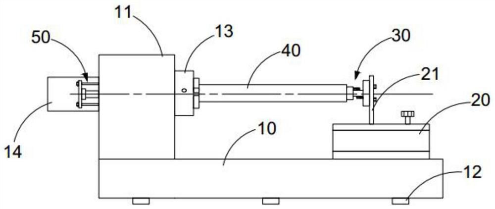
[0043] see Figure 1-8 As shown, a kind of automatic processing fixture for rubber parts manufacturing, including:

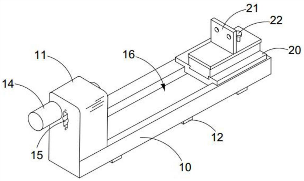
[0044] Bed 10, one side of bed 10 is provided with the bedside box 11 that three-jaw chuck 13 is installed, and the other side is provided with tailstock 20, and the first limit assembly 30 is installed on the tailstock 20, and the tailstock 20 top A supporting connecting plate 21 perpendicular to the horizontal plane is provided, and the supporting connecting plate 21 and the three-jaw chuck 13 face opposite to each other to assemble the first limit assembly 30,

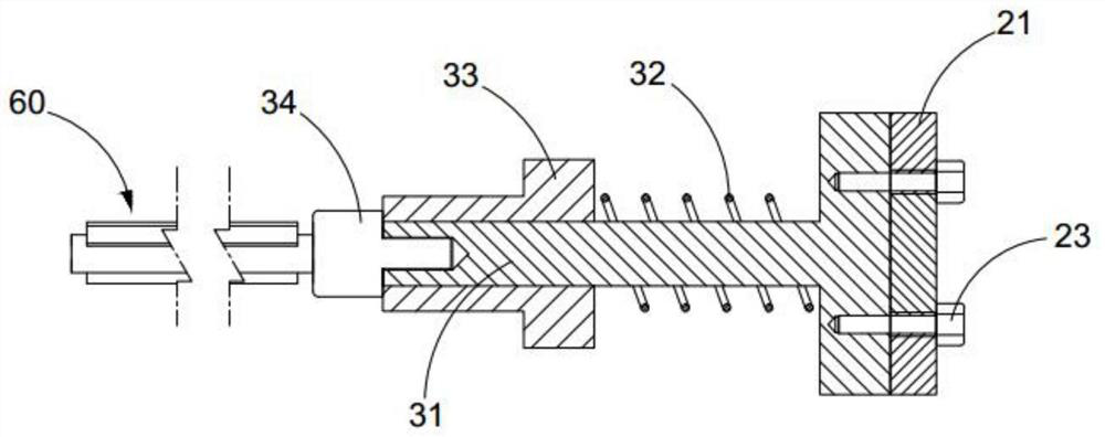
[0045] Wherein, the first limiting assembly 30 includes a limiting main part 31, the limiting main part 31 has a cylindrical structure, and the bottom of the cylindrical structure is provided with an assembly base plate that is mated with the supporting connecting plate 21; the limiting main part 31 The upper sleeve is connected with the limited auxiliary part 33, and the limited auxiliary part 33 is...

Embodiment 2

[0059] A method of using automatic processing fixtures for rubber parts manufacturing:

[0060] - put the third limit assembly 70 into the bedside box 11 to limit the clamping length of the rubber part 40 relative to the three-jaw chuck 13 and make the rubber part 40 coaxial with the three-jaw chuck 13;

[0061] - sliding the tailstock 20 to insert the grinding assembly 60 into the processing hole of the rubber piece 40, and limit the movement range of the rubber piece 40 in the axial direction through the first stopper assembly 30;

[0062] - Control and drive the main motor 14 to start, and the three-jaw chuck 13 drives the clamped rubber part 40 to rotate relative to the grinding assembly 60, and completes the machining of the inner surface of the round hole of the rubber part 40.

[0063] The fixture using method provided by the present invention can realize inner hole processing and fast deburring operation of rubber parts such as shaft sleeves, meet the requirements of p...


PUM


Abstract

The invention discloses a jig for automatic processing of rubber parts, which belongs to the technical field of jigs and jigs. The jig of the invention includes a bed. Frame, the first limit component, installed on the tailstock, the upper part of the tailstock is provided with a support connecting plate perpendicular to the horizontal plane, the support connecting plate is assembled with the first limit component on the opposite surface of the three-jaw chuck, the first limit component It includes the limit main part with a cylindrical structure, and the bottom of the cylindrical structure is provided with an assembly base plate that is connected with the support connecting plate; the limit component is sleeved with a limit accessory, and the limit accessory is a cylindrical sleeve structure. A limiting ring is arranged on the outer surface, a first spring is arranged between the limiting auxiliary part and the limiting main part, and the cylinder end of the limiting main part is connected with a grinding assembly through the connecting base. The fixture of the present invention is used to process the hole wall of the rubber part of the pipe fittings to obtain better surface roughness, the deformation rate of the rubber part during the processing is low, and the yield of the finished product is high.

Description

technical field [0001] The invention belongs to the technical field of fixtures, and in particular relates to a fixture for automatic processing of rubber parts. Background technique [0002] When processing small and medium-sized rubber parts, multiple operations such as cutting, edging, and deburring are required for pipe fittings to obtain a qualified rubber part. In actual operation, due to the high tear resistance and rebound rate of rubber, the processing process It is difficult to meet the processing requirements, for example, the inner surface of the rubber bush is difficult to process, and the roughness is difficult to meet the standard. Contents of the invention [0003] The purpose of the present invention is to provide an automatic processing fixture for the manufacture of rubber parts, which can realize the processing of the hole wall of pipe fittings and rubber parts, obtain better surface roughness, and have low deformation rate and high yield of rubber part...

Claims


Application Information

Patent Timeline
Patent Type & Authority Patents(China)
IPC IPC(8): B24B5/10B24B9/20B24B27/00B24B41/06B24B47/12
CPCB24B5/10B24B9/20B24B27/0076B24B41/062B24B47/12
Inventor 陈尚彪张丽
Owner HUANGSHAN SHANGYI RUBBER & PLASTIC PRODS
Why Eureka
Try Eureka