Eureka AIR delivers breakthrough ideas for toughest innovation challenges, trusted by R&D personnel around the world.

Milling cutter, ultrasonic electric spark milling equipment milling method

An electric spark and ultrasonic technology, applied in the direction of milling machine equipment, electric processing equipment, milling cutter, etc., can solve the problems of tool wear, large cutting force, and increased difficulty in machining, and achieve accurate material removal, reduce cutting load, and high-efficiency discharge Effect

Active Publication Date: 2020-07-10
HUNAN UNIV OF SCI & TECH
View PDF5 Cites 5 Cited by
  • Summary
  • Abstract
  • Description
  • Claims
  • Application Information

AI Technical Summary

Problems solved by technology

[0003] This application is to solve the existing problems. With the rapid development of modern metal processing industry technology, industrial sectors such as machinery manufacturing, electromechanical, weapons and aviation have introduced many high-strength, high-hardness new materials such as high-strength, ultra-high-strength steel, Stainless steel, titanium alloy, chilled cast iron and other difficult-to-machine materials, due to their high strength, high hardness and high strain hardening rate, make it more difficult to process, and the cutting force is large, the temperature rises during processing, and the tool wear is serious. For the technical problems of poor surface quality and low metal removal rate, provide milling cutters, ultrasonic electric spark milling equipment and milling methods

Method used


Image

  • Milling cutter, ultrasonic electric spark milling equipment milling method
  • Milling cutter, ultrasonic electric spark milling equipment milling method
  • Milling cutter, ultrasonic electric spark milling equipment milling method

Examples


Embodiment Construction

[0043] The present application will be described in further detail below through specific embodiments in conjunction with the accompanying drawings.

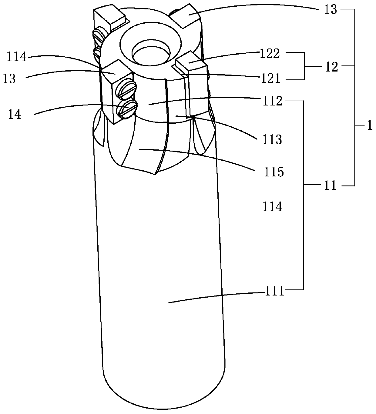
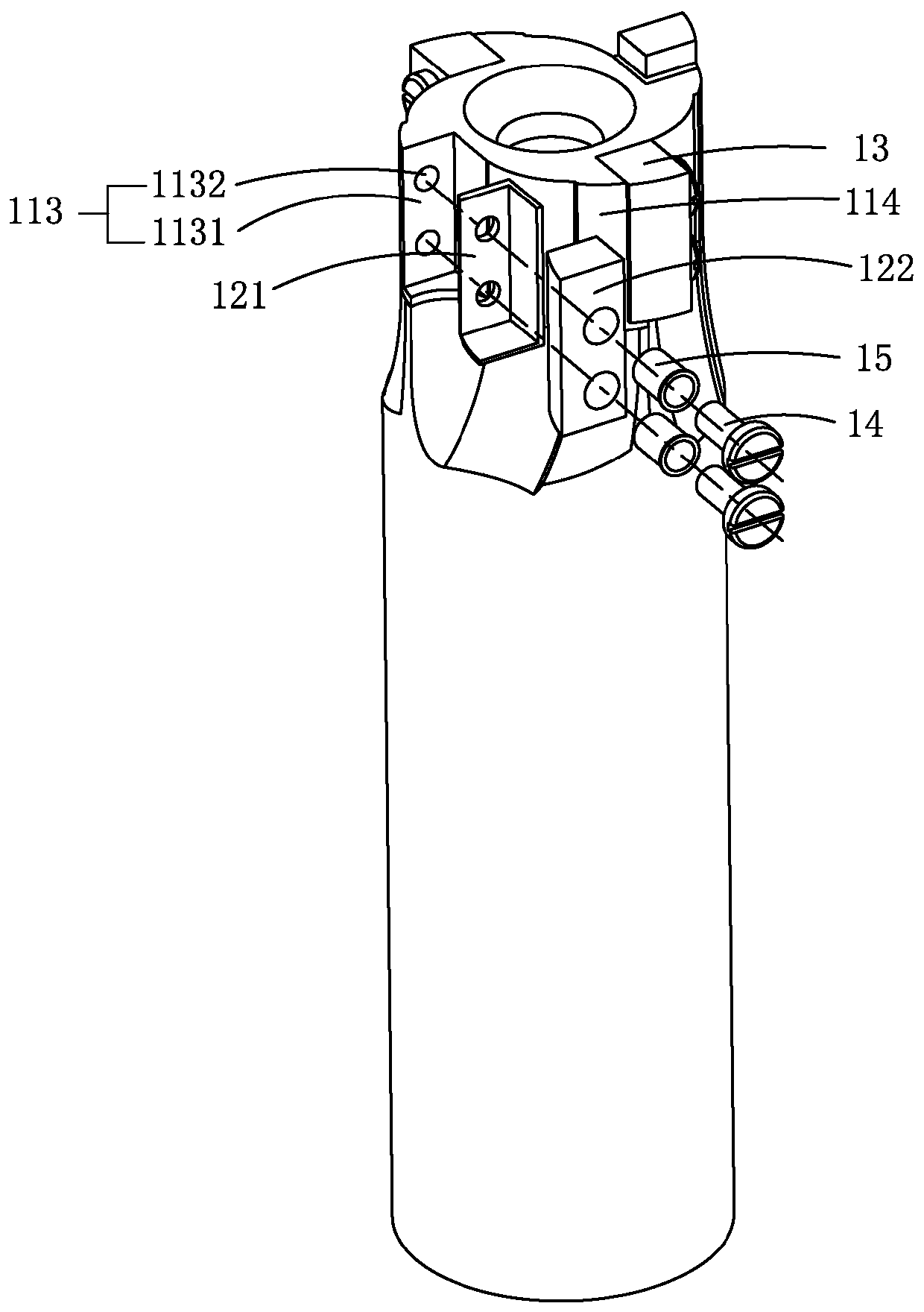
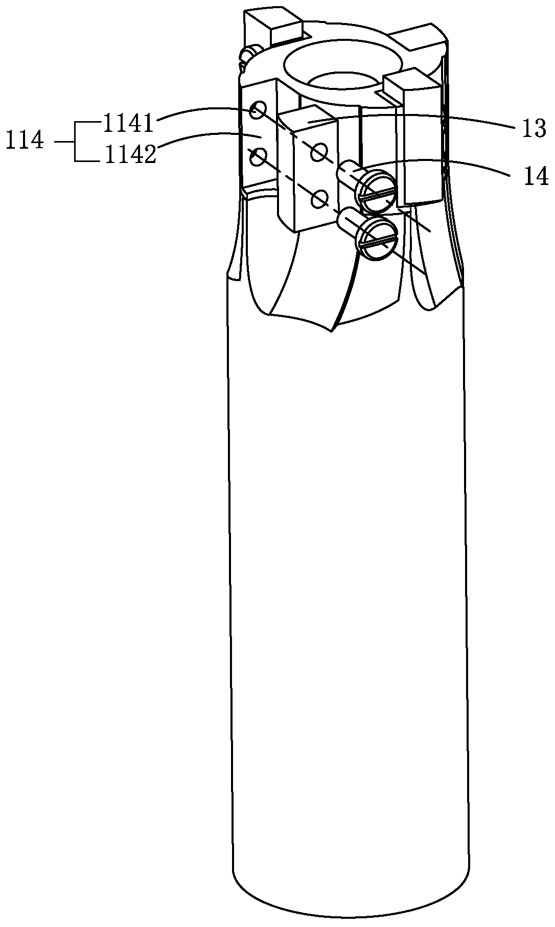
[0044] Such as Figures 1 to 7As shown, a milling cutter 1 includes a cutter body 11 and a blade 12, and is characterized in that: it also includes a discharge electrode 13 arranged on the cutter body 11, and the cutter body 11 includes a cutter bar 111 and is arranged on the cutter bar A cutterhead 112 at one end, the cutterhead 112 is provided with a first fixing part 113 and a second fixing part 114 at intervals along its peripheral direction, the blade 12 is arranged on the first fixing part 113, and the discharge electrode 13 is located on the second fixing part 114, and the maximum distance D1 between the blade 12 and the cutter head rotation axis is greater than the maximum distance D2 between the discharge electrode 13 and the cutter head rotation axis, and the blade 12 is far away from the cutter head The maximum heigh...


PUM


Abstract

The invention discloses a milling cutter. The milling cutter comprises a cutter body, a cutter blade and a discharge electrode arranged on the cutter body, wherein the cutter body comprises a cutter bar and a cutterhead arranged at one end of the cutter bar, a first fixing part and a second fixing part are arranged in the peripheral direction of the cutterhead in a bulging manner at an interval, the cutter blade is arranged at the first fixing part, the discharge electrode is arranged at the second fixing part, the maximum distance D1 between a position of the cutter blade and a cutterhead rotating shaft is larger than the maximum distance D2 between a position of the discharge electrode and the cutterhead rotating shaft, and the maximum height H1 between the cutterhead and the end, away from the cutterhead, of the cutter blade is larger than the maximum height H2 between the cutterhead and the end, away from the cutterhead, of a position of the discharge electrode. The discharge electrode electrically breaks down a dielectric medium between the discharge electrode and a metal part to produce high temperature, characteristics of a to-be-processed surface change, the surface of themetal part is softened, a free-cutting denatured layer is produced, and finally, the denatured layer and a thin substrate are cut off by the cutter blade.

Description

【Technical field】 [0001] The present application relates to the field of milling, in particular to a milling cutter, ultrasonic electric spark milling equipment and a milling method. 【Background technique】 [0002] Existing With the rapid development of modern metal processing industry technology, industrial sectors such as machinery manufacturing, electromechanical, weapons and aviation have introduced many high-strength, high-hardness new materials such as high-strength, ultra-high-strength steel, stainless steel, titanium alloy Difficult-to-machine materials such as chilled cast iron, due to their high strength, high hardness and high strain hardening rate, make it more difficult to process, and during processing, the cutting force is large, the temperature rises, the tool wears seriously, and the processed surface quality is poor. , low metal removal rate. 【Content of invention】 [0003] This application is to solve the existing problems. With the rapid development of...

Claims


Application Information

Patent Timeline
Patent Type & Authority Applications(China)
IPC IPC(8): B23H5/04B23H3/04B23C5/00
CPCB23P23/02B23H1/00B23H9/00
Inventor 李常平黄磊高泰祖李树健李鹏南牛秋林邱新义
Owner HUNAN UNIV OF SCI & TECH
Why Eureka
Eureka Blog
Learn More