
Double rotating shaft type electric servo flexible skew-rolling mill

A technology of electric servo and skew rolling mill, which is applied in the direction of metal rolling stand, metal rolling mill stand, and driving device for metal rolling mill, which can solve the problems of high-quality shaft parts production, poor product quality stability, and forming equipment Complicated structure and other problems, to achieve the effect of reasonable overall equipment layout, expanded rolling range and high degree of automation

Active Publication Date: 2020-06-19
UNIV OF SCI & TECH BEIJING
View PDF7 Cites 4 Cited by
  • Summary
  • Abstract
  • Description
  • Claims
  • Application Information

AI Technical Summary

Problems solved by technology

[0003] At present, the forming processes of large-scale shaft parts mainly include: first, free forging and rapid forging are used. This process does not need to design special molds, and the production flexibility is high, but it has low production efficiency, low product precision, low degree of automation, and stable product quality. Poor performance and other problems restrict the production of high-quality shaft parts; the second is radial forging, which has high precision and is currently the main method for forming large shaft parts. High cost and other issues; the third is cross wedge rolling forming, which can be formed with high efficiency and precision through the development of product molds, but there are problems such as large mold size, high processing cost, and inflexible production.

Method used


Image

  • Double rotating shaft type electric servo flexible skew-rolling mill
  • Double rotating shaft type electric servo flexible skew-rolling mill
  • Double rotating shaft type electric servo flexible skew-rolling mill

Examples


Embodiment Construction

[0070] Specific embodiments of the present invention will be described in detail below in conjunction with specific drawings. It should be noted that the technical features or combinations of technical features described in the following embodiments should not be regarded as isolated, and they can be combined with each other to achieve better technical effects. In the drawings of the following embodiments, the same symbols appearing in each drawing represent the same features, which can be applied in different embodiments.

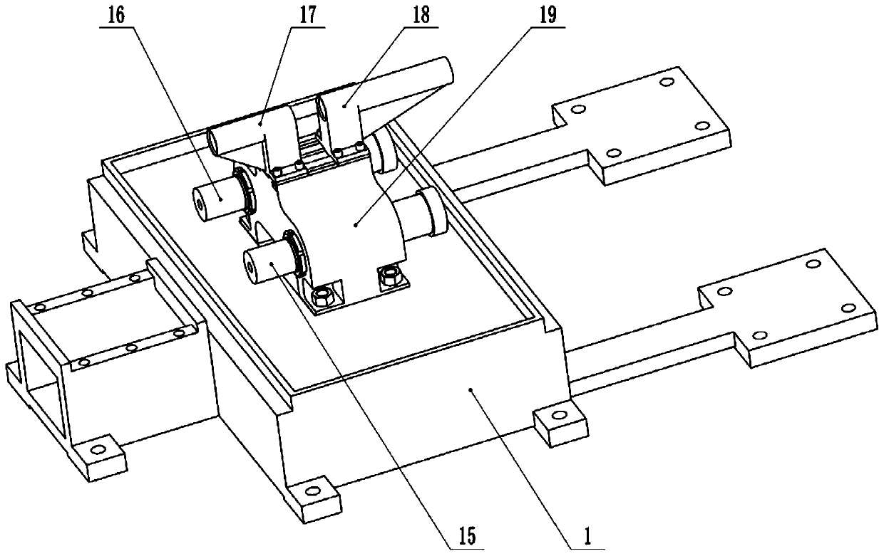
[0071] An embodiment of the present invention is a double-shaft electric servo flexible skew rolling mill, which includes a base unit, a frame synchronization unit, two rolls, an axial thrust system, a roll distance adjustment system, a counterweight unit, a two-roll inclination angle adjustment system and two rolls. Spindle rotation system.

[0072] The two-spindle rotation system is used to install and drive two rolls to rotate around their main shafts;...


PUM


Abstract

The invention relates to the technical field of metal plastic forming process and equipment, and provides a double rotating shaft type electric servo flexible skew-rolling mill. The double rotating shaft type electric servo flexible skew-rolling mill includes a base unit, a machine frame synchronization unit, two rolls, two main shaft rotation systems, an axial thrust system, two roll inclinationangle adjustment systems, a roll pitch adjustment system and a counterweight unit. The base unit supports a whole machine body of the skew-rolling mill. The axial thrust system exerts axial thrust ona blank. The machine frame synchronization unit ensures that the two machine frames are pressed down synchronously in a centring mode. The two main shaft rotation systems drive the rotation of the tworolls. The inclination angle adjustment system adjusts the inclination angle between the axis line of the two rolls and the axis line of the blank, the roll pitch adjustment system adjusts the roll pitch of the two rolls, and the counterweight unit reduces the torque required by the inclination angle adjustment system. Driven by a servo motor and controlled by a servo driver, the double rotatingshaft type electric servo flexible skew-rolling mill has the advantages of compact structure, high degree of automation, low vibration noise, wide rolling range and the like, and is suitable for flexible skew rolling of large shaft parts.

Description

technical field [0001] The invention relates to the technical field of metal plastic forming technology and equipment, in particular to a double-shaft electric servo flexible skew rolling mill. Background technique [0002] Large-scale shaft parts are one of the key components of major equipment manufacturing. They are used for power transmission and motion realization of large-scale equipment. Cannon barrels, etc. Large-scale shaft parts are generally subjected to complex loads such as bending, torsion, impact, and vibration under high-speed and heavy-duty conditions. Therefore, their production costs, forming accuracy, and performance quality will directly affect rail transportation, steel rolling machinery, hydropower, and ships. The industrial base of manufacturing and other industries is the prerequisite for the development of heavy-duty advanced equipment manufacturing. [0003] At present, the forming processes of large-scale shaft parts mainly include: first, free ...

Claims


Application Information

Patent Timeline
IPC IPC(8): B21B13/00B21B31/24B21B35/12
CPCB21B13/008B21B31/24B21B35/12
Inventor 王宝雨林龙飞刘晋平吕红亮
Owner UNIV OF SCI & TECH BEIJING
Learn More