Eureka AIR delivers breakthrough ideas for toughest innovation challenges, trusted by R&D personnel around the world.

Silicon micro-gyroscope data acquisition device based on wireless transmission

A silicon micro-gyroscope and data acquisition technology, applied in gyroscope/steering sensing equipment, measuring device, gyro effect for speed measurement, etc., can solve uneven temperature distribution, gyroscope output signal error, slip ring frosting, etc. problem, achieve the effects of reducing uneven temperature distribution, fast and accurate acquisition, and long transmission distance

Pending Publication Date: 2020-05-08
NANJING UNIV OF SCI & TECH
View PDF3 Cites 1 Cited by
  • Summary
  • Abstract
  • Description
  • Claims
  • Application Information

AI Technical Summary

Problems solved by technology

The working temperature of the gyroscope is -40°C to 85°C. At a lower temperature, the slip ring will produce frost and other phenomena, which will cause bit errors, which will cause a large error in the output signal of the gyroscope.
[0006] In addition, during the test process, the high and low temperature chamber was used to simulate the changing working temperature of the gyroscope. Due to the uneven temperature distribution inside the high and low temperature chamber, it was impossible to accurately perceive the actual working temperature of the gyroscope, which made it more difficult to correctly establish the temperature error model. difficulty
[0007] Therefore, there are two problems in the prior art: on the one hand, when the gyroscope is tested, since the silicon microgyroscope is directly connected to the computer through the slip ring, the friction between the slip ring and the turntable produces code errors; When considering the temperature characteristics of the gyroscope, due to the uneven temperature distribution, it is impossible to accurately obtain the temperature information of the gyroscope

Method used


Image

  • Silicon micro-gyroscope data acquisition device based on wireless transmission
  • Silicon micro-gyroscope data acquisition device based on wireless transmission
  • Silicon micro-gyroscope data acquisition device based on wireless transmission

Examples


Embodiment Construction

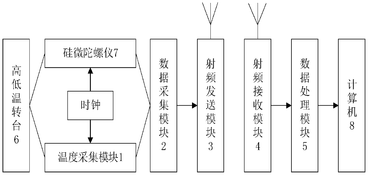
[0027] Such as figure 1 Shown, the present invention is based on the silicon microgyroscope data acquisition device of wireless transmission, comprises:

[0028] The temperature acquisition module 1 is used to detect the temperature of the high and low temperature box and collect the real-time temperature of the silicon micro gyroscope;

[0029] The data acquisition module 2 is used to collect the output of the silicon micro gyroscope and the temperature acquisition module, and perform analog-to-digital conversion processing on it;

[0030] The radio frequency sending module 3 is used for modulating the information of the data acquisition module, and converting the modulated signal into a radio frequency signal suitable for wireless transmission;

[0031] The radio frequency receiving module 4 is used for receiving the information transmitted by the radio frequency sending module and demodulating it;

[0032] The data processing module 5 is used to process the information of...


PUM


Abstract

The invention discloses a silicon micro-gyroscope data acquisition device based on wireless transmission. The silicon micro-gyroscope data acquisition device is small in size, simple to operate and precise in output. The disclosed silicon micro-gyroscope data acquisition device based on wireless transmission comprises a temperature acquisition module (1), a data acquisition module (2), a radio frequency transmitting module (3), a radio frequency receiving module (4) and a data processing module (5), wherein an input end of the temperature acquisition module (1) is respectively contacted with asilicon micro gyroscope and a high-low temperature box; an output end of the temperature acquisition module (1) is connected with the data acquisition module (2); an output end of the data acquisition module (2) is connected with an input end of the radio frequency transmitting module (3); the radio frequency transmitting module (3) is connected with the radio frequency receiving module (4) by means of radio frequency signals; and an output end of the radio frequency receiving module (4) is connected with an input end of the data processing module.

Description

technical field [0001] The invention belongs to the technical field of silicon microgyroscope data collection and testing, in particular to a silicon microgyroscope data collection device based on wireless transmission with high accuracy. Background technique [0002] Due to the advantages of light weight, small size, low cost and high reliability, silicon micro gyroscopes are widely used in the fields and occasions of navigation guidance, aerospace, and guided shells. Micromechanical gyroscopes are divided into silicon material gyroscopes and quartz and ceramic material gyroscopes according to materials. Using silicon wafers as substrates can realize the integration of gyroscope technology and semiconductor technology, which is in line with the future development trend of gyroscopes. [0003] There are many factors that affect the output accuracy of the gyroscope, and temperature error is one of the main sources of error. Silicon material is a heat-sensitive material, and...

Claims


Application Information

Patent Timeline
Patent Type & Authority Applications(China)
IPC IPC(8): G01C19/5776
CPCG01C19/5776
Inventor 张萌王虹沈迪宇吴妍吕东
Owner NANJING UNIV OF SCI & TECH
Why Eureka
Eureka Blog
Learn More