Numerical control machine tool clamping structure

A clamping structure, CNC machine tool technology, applied in the direction of clamping, metal processing mechanical parts, supports, etc., can solve the problems of unstable clamping, round bar rolling, etc., to facilitate accurate positioning, improve service life, improve Effects of Stability and Reliability

Inactive Publication Date: 2020-05-01
青海高等职业技术学院
View PDF9 Cites 3 Cited by
  • Summary
  • Abstract
  • Description
  • Claims
  • Application Information

AI Technical Summary

Problems solved by technology

[0005] Although the above solution realizes the variable diameter clamping of the workpiece through the detachable connection between the fixed plate and the bolt, in actual use, the fixed plate is only clamped by the driving force of the motor when the motor is pushed, but the circular bar During the clamping process, the round bar is easy to roll when the fixed plate is advanced, resulting in unstable clamping

Method used


Image

  • Numerical control machine tool clamping structure
  • Numerical control machine tool clamping structure

Examples


Embodiment Construction

[0027] The technical solutions in the embodiments of the present invention will be clearly and completely described below with reference to the accompanying drawings in the embodiments of the present invention. Obviously, the described embodiments are only a part of the embodiments of the present invention, but not all of the embodiments. Based on the embodiments of the present invention, all other embodiments obtained by those of ordinary skill in the art without creative efforts shall fall within the protection scope of the present invention.

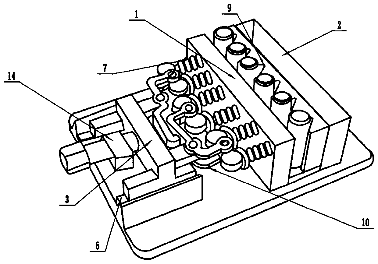
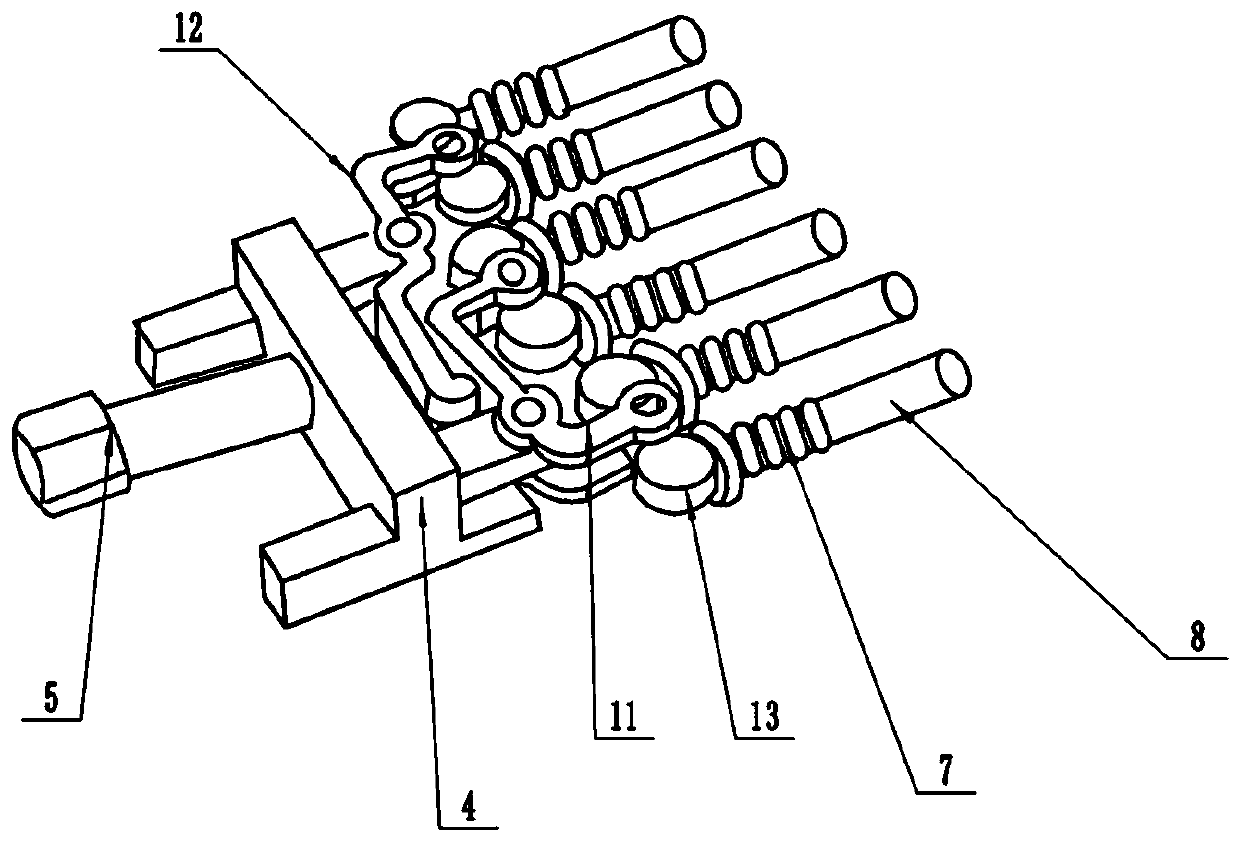
[0028] Reference numerals in the accompanying drawings include: front support plate 1, rear support plate 2, push abutment device 3, transverse plate 4, screw 5, slide rail 6, tension spring 7, through shaft 8, corrugated placement groove 9, The offset adjustment device 10 , the first offset plate 11 , the second offset plate 12 , the turntable 13 , and the rectangular block 14 .

[0029] The example is basically as attached figure 1...


PUM


Abstract

The invention discloses a numerical control machine tool clamping structure in the field of automatic clamps to overcome the defect of unstable round bar clamping in the prior art. The clamping structure comprises a workbench, a front support plate and a rear support plate are fixed to the surface of the workbench, a gap for placing a round material is formed between the front support plate and the rear support plate, through holes are formed in the surface of the front support plate, the through holes are formed in the surface of the front support plate in a transverse row, and a pushing abutting device is arranged close to the front support plate. The pushing abutting device comprises a transverse plate, a screw rod and a sliding rail, wherein tension springs are arranged between the transverse plate and the through holes, the tension springs correspond to the through holes one to one, the diameter of the tension springs is larger than the aperture of the through holes, and through shafts penetrate through the tension springs. According to the device, the gap formed by the front support plate and the rear support plate is used for primary clamping of the round material, then thetransverse plate and the through shafts are sequentially driven by the screw rod to carry out secondary clamping on the round material, and the clamping stability and reliability are improved.

Description

technical field [0001] The invention belongs to the field of automated fixtures, in particular to a clamping structure of a numerically controlled machine tool. Background technique [0002] A machine tool refers to a machine that makes a machine, also known as a work machine or a machine tool, and is customarily referred to as a machine tool. Generally divided into metal cutting machine tools, forging machine tools and woodworking machine tools. There are many ways to process mechanical parts in modern machinery manufacturing: in addition to cutting, there are casting, forging, welding, stamping, extrusion, etc., but for parts with high precision and fine surface roughness requirements, generally need to be in The final machining is performed by cutting on the machine tool. Machine tools play an important role in the modernization of the national economy. [0003] Fixture is a device used to fix the processing object in the process of machinery manufacturing, so that it ...

Claims


Application Information

Patent Timeline
Patent Type & Authority Applications(China)
IPC IPC(8): B23Q3/06
CPCB23Q3/061
Inventor 李有新关婷婷李志强多杰马世辉
Owner 青海高等职业技术学院
Why Eureka
Try Eureka