
SEM in-situ tensile test method for researching interface fracture behavior of metal matrix and ceramic film layer

An in-situ stretching and metal matrix technology, applied in the direction of applying stable tension/pressure to test material strength, preparation of test samples, and measurement devices, can solve the problem that is not suitable for revealing the fracture of brittle film layers and plastic matrix systems Process and mechanism analysis and other issues, to achieve the effect of visual representation and wide applicability, easy operation and high success rate

Active Publication Date: 2020-04-07
HARBIN INST OF TECH
View PDF7 Cites 0 Cited by
  • Summary
  • Abstract
  • Description
  • Claims
  • Application Information

AI Technical Summary

Problems solved by technology

[0003] The present invention aims to solve the problem that the existing SEM in-situ tensile samples and tensile test methods of homogeneous materials are not suitable for revealing the fracture process and mechanism analysis of the brittle film layer and the plastic matrix system, and provides a method for studying the metal matrix and the plastic matrix system. SEM in situ tensile test method of interface fracture behavior of ceramic film

Method used


Image

  • SEM in-situ tensile test method for researching interface fracture behavior of metal matrix and ceramic film layer
  • SEM in-situ tensile test method for researching interface fracture behavior of metal matrix and ceramic film layer
  • SEM in-situ tensile test method for researching interface fracture behavior of metal matrix and ceramic film layer

Examples


specific Embodiment approach 1

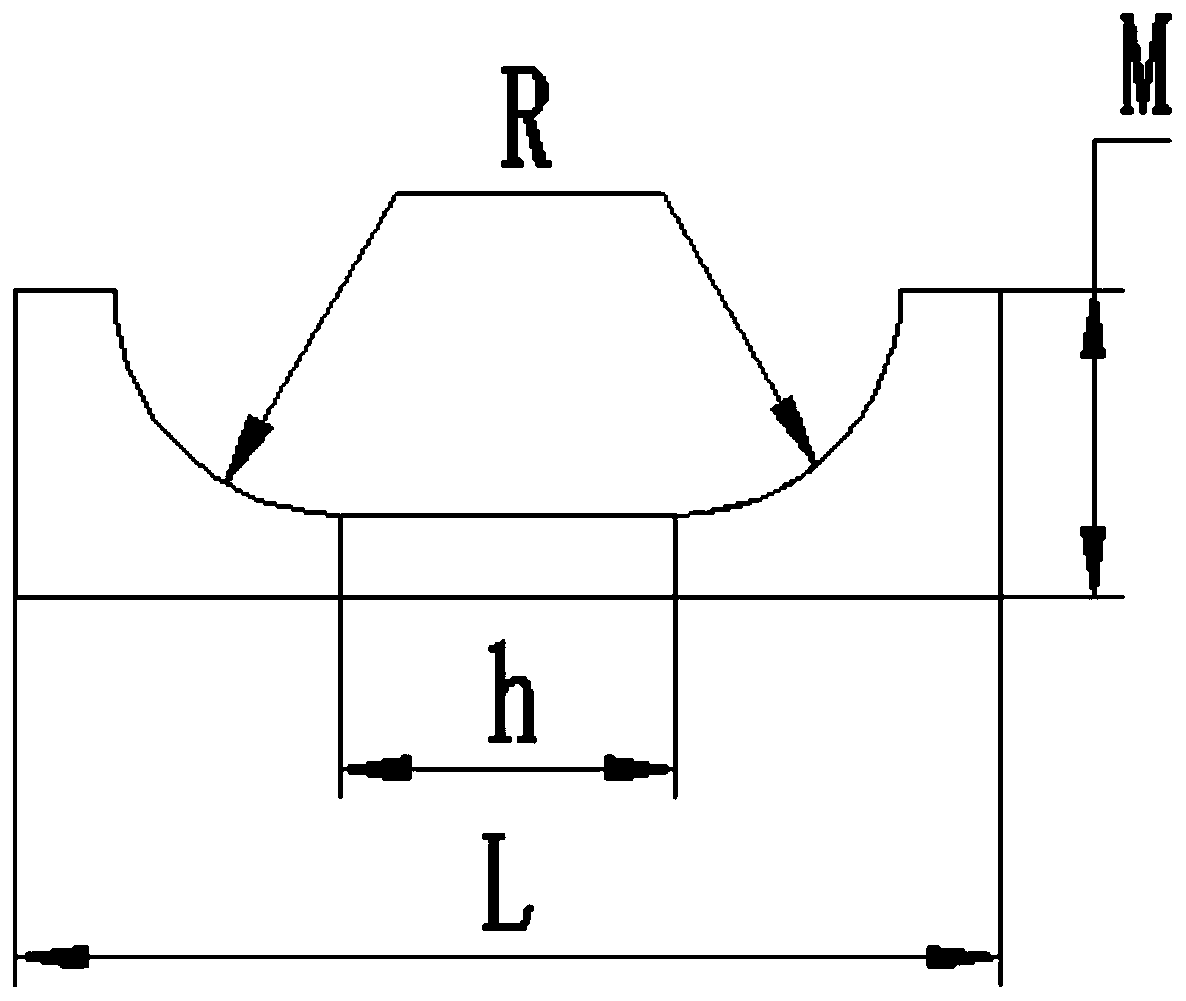
[0023] Specific implementation mode one: combine figure 1 Specifically, this embodiment is a SEM in-situ tensile test method for studying the fracture behavior of the metal substrate and the ceramic film layer interface, which is completed according to the following steps:

[0024] 1. Preparation of in-situ tensile specimens:

[0025] Open a U-shaped notch in the middle of one side of the long-side section of the plastic metal substrate covered with a ceramic film layer to obtain an SEM in-situ tensile sample;

[0026] The shape of the plastic metal substrate covered with a ceramic film layer is rectangular, the thickness is 0.2mm-5mm, the length is L=20mm-40mm, and the width is M=5mm-15mm;

[0027] The length of the straight section of the bottom edge of the U-shaped notch is h=10mm-30mm, the depth is equal to the radius of the transition fillet, the radius of the transition fillet is R=5mm-10mm, and the length of the opening is (h+2R)mm;

[0028] 2. Sample processing:

[...

specific Embodiment approach 2

[0040] Specific embodiment 2: The difference between this embodiment and specific embodiment 1 or 2 is: in step 2, use 600#, 800# for the long side section of the opposite side of the U-shaped notch in the SEM in-situ tensile sample. , 1200# and 2000# sandpaper for polishing. Others are the same as in the first or second embodiment.

specific Embodiment approach 3

[0041] Specific embodiment three: the difference between this embodiment and one of the specific embodiments one or two is: in step three, the sample clamping part in the test bench is adjusted, so that the gold-sprayed side of the SEM in-situ tensile sample after spraying gold is positive After aligning the scanning electron microscope lens, mark several positions on the gold-sprayed side by focusing the electron beam. Others are the same as in the first or second embodiment.


PUM

PropertyMeasurementUnit
thicknessaaaaaaaaaa
lengthaaaaaaaaaa
thicknessaaaaaaaaaa

Abstract

The invention discloses an SEM in-situ tensile test method for researching an interface fracture behavior of a metal matrix and a ceramic film layer, and relates to an SEM in-situ tensile test method.The invention aims to solve the problem that an SEM in-situ tensile sample and a tensile test mode of an existing homogeneous material are not suitable for revealing the fracture process and mechanism analysis of a brittle film layer and a plastic matrix system. The method comprises the following steps: 1, preparation of an in-situ tensile sample; 2, sample treatment; and 3, recording of mechanical property parameters and microtopography in real time in the in-situ tensile process, so as to finish the SEM in-situ tensile test method for researching the interface fracture behavior of the metalmatrix and the ceramic film layer.

Description

technical field [0001] The invention relates to a SEM in-situ tensile test method. Background technique [0002] In recent years, the substrate film structure has always been a hot spot in academia and industry. Among them, the brittle film and plastic matrix system has been widely used in the fields of aerospace, electronics, medical treatment, chemical industry, shipbuilding and automobiles due to its unique thermal stability, chemical inertness and good wear resistance and corrosion resistance. Applications (including: physical vapor deposition, chemical vapor deposition, sol-gel, thermal spraying, cold spraying, chemical conversion, laser cladding, micro-arc oxidation and anodic oxidation and other preparation techniques). However, when served under the condition of tensile load, the strain of the brittle film layer is significantly different from that of the plastic matrix, which makes the material prone to fracture and failure, endangering the reliability and life of ...

Claims


Application Information

Patent Timeline
Patent Type & Authority Applications(China)
IPC IPC(8): G01N3/08G01N23/2251G01N23/2202G01N1/28G01N1/32
CPCG01N1/286G01N1/32G01N3/08G01N23/2202G01N23/2251G01N2203/0017
Inventor 魏大庆邹永纯杜青郭舒张宝友来忠红
Owner HARBIN INST OF TECH
Learn More