Ultralow-temperature in-situ stretching table and scanning electron microscope ultralow-temperature in-situ stretching test system

A technology of in-situ stretching and scanning electron microscopy, applied in the direction of applying stable tension/pressure to test the strength of materials, measuring devices, instruments, etc., can solve problems such as fracture, dynamic capture of material crack initiation, etc., and achieve precise control and visual representation And the effect of wide applicability and precise temperature

Active Publication Date: 2021-07-20
HARBIN INST OF TECH
View PDF15 Cites 3 Cited by
  • Summary
  • Abstract
  • Description
  • Claims
  • Application Information

AI Technical Summary

Problems solved by technology

[0004] The purpose of the present invention is to solve the problem that the traditional tensile performance test cannot dynamically capture the crack initiation, expansion, necking and fracture of the material in the ultra-low temperature environment, and further provide an ultra-low temperature in-situ stretching table and scanning electron microscope ultra-low temperature in-situ stretching test system

Method used


Image

  • Ultralow-temperature in-situ stretching table and scanning electron microscope ultralow-temperature in-situ stretching test system
  • Ultralow-temperature in-situ stretching table and scanning electron microscope ultralow-temperature in-situ stretching test system
  • Ultralow-temperature in-situ stretching table and scanning electron microscope ultralow-temperature in-situ stretching test system

Examples


specific Embodiment approach 1

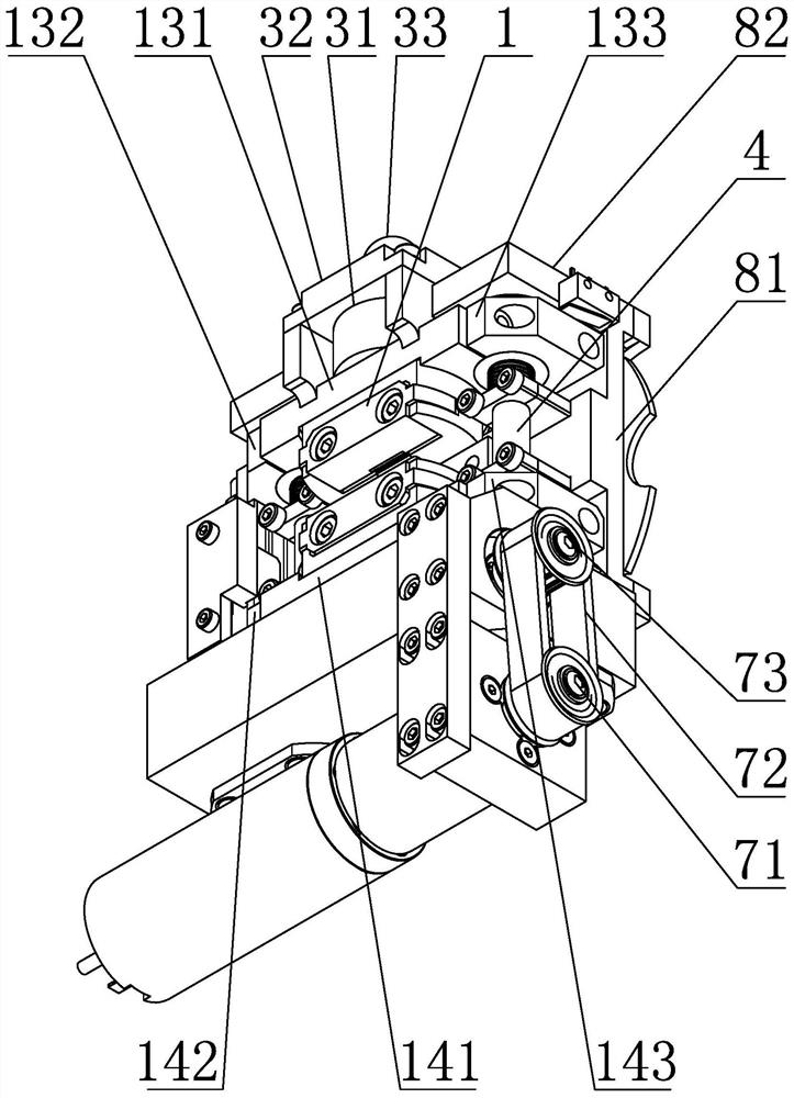
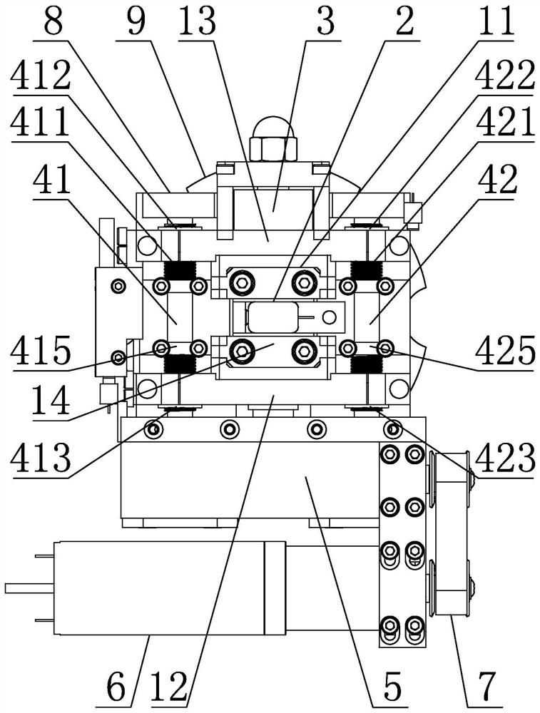
[0028] Specific implementation mode one: combine Figure 2 to Figure 9 Describe this embodiment, an ultra-low temperature in-situ stretching table of this embodiment, which includes a sample holder 1, a cryogenic refrigerator 2, a tension sensor assembly 3, a moving screw mechanism 4, a driving device, a frame 8 and an electron microscope The platform connection plate 9 and the frame 8 include a base plate 81 and two side plates 82, the base plate 81 is arranged horizontally, and the two side plates 82 are vertically arranged on both sides of the upper end surface of the base plate 81, and the base plate 81 and the two side plates 82 are integrated structure, each side plate 82 is provided with two shaft holes reserved for screw screws, and the four shaft holes reserved for screw screws on the two side plates 82 are arranged opposite to each other. The device 2 is installed in the reserved square hole of the refrigerator of the base plate 81, and the electron microscope stage ...

specific Embodiment approach 2

[0029] Specific implementation mode two: combination Figure 6 to Figure 9 Describe this embodiment, the driving device of this embodiment comprises speed reducer 5, motor 6 and belt transmission mechanism 7, speed reducer 5 is installed on the outer end surface of a side plate 82 of frame 8, two output shafts of speed reducer 5 Connect with the first lead screw assembly 41 and the second lead screw assembly 42 respectively, the motor 6 is installed on the speed reducer 5, the belt transmission mechanism 7 includes a driving pulley 71, a conveyor belt 72 and a driven pulley 73, and the driving pulley 71 is installed On the output shaft of the motor 6 , the driven pulley 73 is installed on the input shaft of the speed reducer 5 , and the driving pulley 71 is connected with the driven pulley 73 through the transmission belt 72 . In this way, the output shaft of the motor 6 drives the driving pulley 71 to rotate, and the driving pulley 71 drives the driven pulley 73 to rotate thr...

specific Embodiment approach 3

[0030] Specific implementation mode three: combination Figure 2 to Figure 5 To illustrate this embodiment, the first screw assembly 41 of this embodiment includes a screw shaft a411, an upper slider a412, a lower slider a413, two bearings a414 and two screw support seats a415, and the two screw shafts a411 The ends are respectively inserted into the reserved shaft holes of the screw corresponding to the two side plates 82, the bearing a414 is provided between the shaft end of the screw shaft a411 and the corresponding side plate 82, and the two ends of the screw shaft a411 are respectively provided with left-handed threads and right-handed thread, the middle part of the screw shaft a411 is the optical axis, the upper slider a412 and the lower slider a413 are screwed on the two ends of the screw shaft a411 respectively, and the two screw support seats a415 are sleeved on the screw shaft a411 The middle optical axis is connected with the bottom plate 81; the second screw assemb...


PUM


Abstract

The invention discloses an ultralow-temperature in-situ stretching table and a scanning electron microscope ultralow-temperature in-situ stretching testing system, and relates to the field of ultralow-temperature mechanical property testing. According to the invention, the problem that crack initiation, expansion, necking and fracture of a material in an ultralow temperature environment cannot be dynamically captured in a traditional tensile property test is solved. A low-temperature refrigerator is installed in a refrigerator reserved square hole of a bottom plate, a first lead screw assembly and a second lead screw assembly are arranged above the bottom plate side by side, the two ends of the first lead screw assembly and the two ends of the second lead screw assembly are rotationally connected with two side plates correspondingly, and a driving device is installed on the outer end face of one side plate of a rack. The two power output ends of the driving device are connected with the first lead screw assembly and the second lead screw assembly correspondingly. The first clamp assembly is installed on the end face of the side, close to the low-temperature refrigerator, of the first sliding block fixing assembly, and the second clamp assembly is installed on the end face of the side, close to the low-temperature refrigerator, of the second sliding block fixing assembly. The ultralow-temperature in-situ stretching table and the scanning electron microscope ultralow-temperature in-situ stretching testing system are used for dynamically capturing crack initiation, expansion, necking and fracture of the material in an ultralow-temperature environment.

Description

technical field [0001] The invention relates to the field of ultra-low temperature mechanical property testing, in particular to an ultra-low temperature in-situ stretching platform and a scanning electron microscope ultra-low temperature in-situ stretching test system. Background technique [0002] With the rapid development of science and technology, the requirements for materials (metals, ceramics, polymers, composite materials and coating materials) are becoming more and more stringent, especially in the fields of aerospace, petroleum and petrochemical industries, when materials are used in low temperature environments When the temperature is high, the properties of the material, especially the mechanical properties, will show significant changes. In general, as the temperature decreases, the strength and hardness of the material increase, while the plasticity and toughness decrease. Metal materials may experience a sharp drop in plasticity and toughness at a certain lo...

Claims


Application Information

Patent Timeline
Patent Type & Authority Applications(China)
IPC IPC(8): G01N3/18G01N3/06G01N3/04
CPCG01N3/18G01N3/06G01N3/04G01N2203/0017G01N2203/0075G01N2203/0228G01N2203/0423G01N2203/0647G01N2203/0064G01N2203/0066G01N2203/0067
Inventor 邹永纯杜青唐光泽魏大庆郭舒张宝友来忠红陈伟
Owner HARBIN INST OF TECH
Why Eureka
Try Eureka