
Waste incineration energy-saving flue gas ultralow purification system

A waste incineration and purification system technology, applied in gas treatment, chemical instruments and methods, dispersed particle filtration, etc., can solve the problems of reducing the efficiency of the whole plant and wasting energy, and achieve high-grade energy saving, high operating costs, and reduced consumption Effect

Pending Publication Date: 2020-03-27
SHANGHAI SUS ENVIRONMENT
View PDF7 Cites 17 Cited by
  • Summary
  • Abstract
  • Description
  • Claims
  • Application Information

AI Technical Summary

Problems solved by technology

In order to meet the reaction temperature of the catalyst, both of these two processes need to add SGH and use steam to increase the flue gas temperature, which greatly wastes energy, increases the plant power consumption rate (the plant power consumption rate increases by about 5%), and reduces the overall plant efficiency

Method used


Image

  • Waste incineration energy-saving flue gas ultralow purification system
  • Waste incineration energy-saving flue gas ultralow purification system
  • Waste incineration energy-saving flue gas ultralow purification system

Examples


Embodiment 1

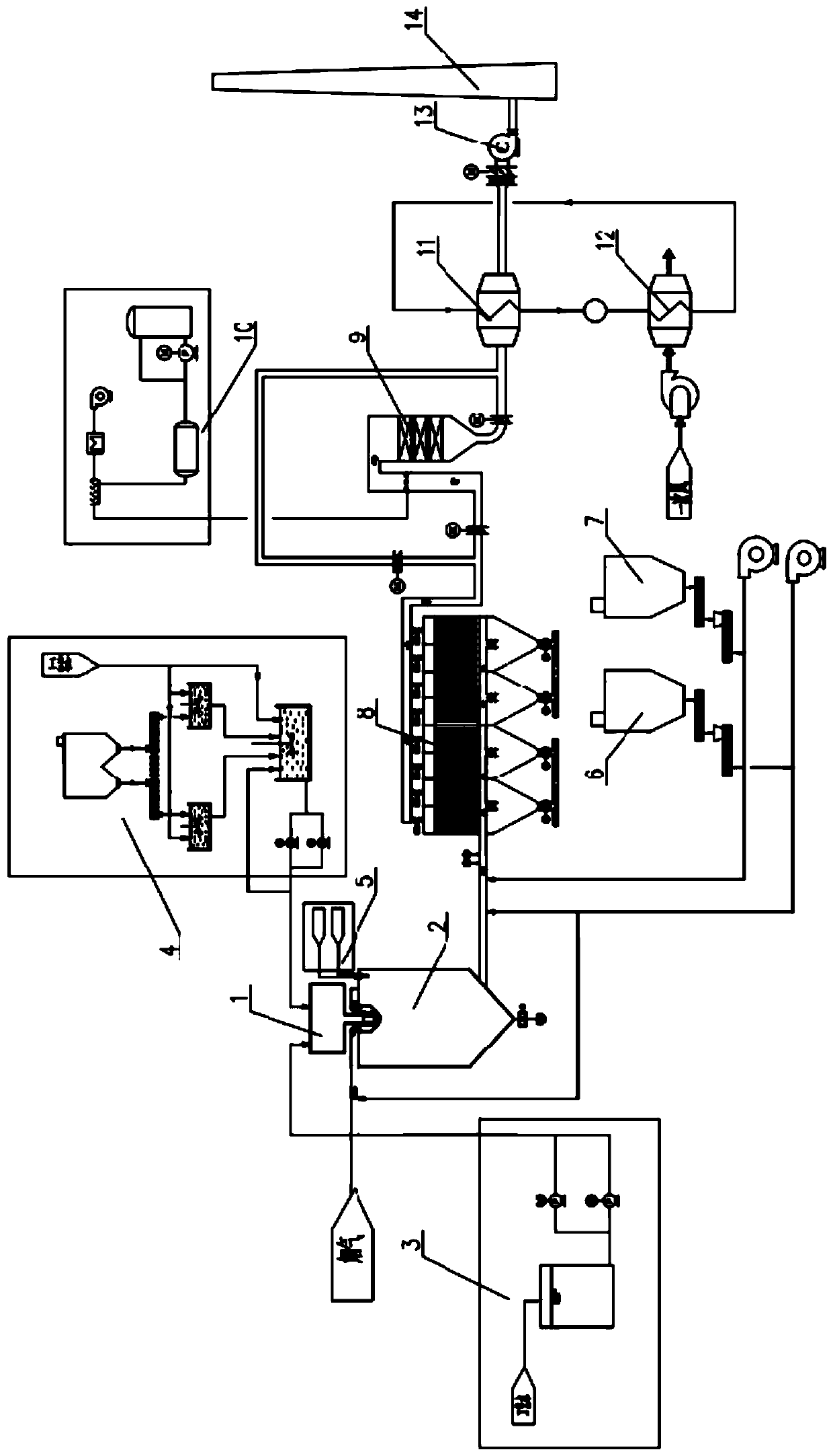
[0038] The present invention is a waste incineration energy-saving flue gas ultra-low emission system, and its system flow chart is as follows figure 1 As shown, it includes SNCR denitrification device (not shown in the schematic diagram, which belongs to furnace denitrification), semi-dry reaction tower 2, sodium carbonate slurry system 4, atomizer cooling water system 3, two-fluid atomization cooling water system 5, carbonic acid Hydrogen and sodium dry powder injection device 6, activated carbon injection device 7, bag filter 8, SCR reactor 9, ammonia water storage and injection device 10, water medium flue gas cooler 11 (also known as: MGGH11), water medium flue gas Heater 12 (also known as MGGH12), induced draft fan 13, chimney 14. The upper part of the semi-dry reaction tower 2 is provided with a high-speed rotary sprayer 1, and the rotary sprayer 1 is connected with a sodium carbonate slurry system 4 and an atomizer cooling water system 3. The top of the semi-dry reacti...

Embodiment 1

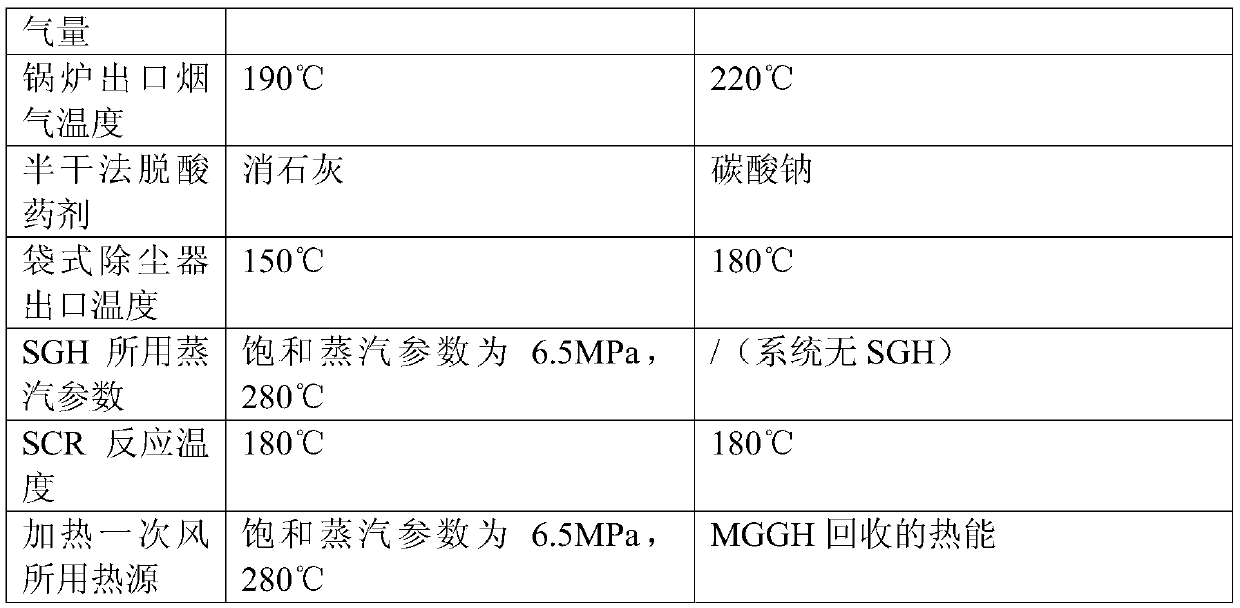
[0045] Taking a waste incineration power plant as an example, with the flue gas combined treatment process of "semi-dry deacidification + dry deacidification + activated carbon adsorption + bag filter + SGH + SCR" using the existing technology, the pollutant discharge meets Standard requirements are compared under the same premise. The basic design parameters are shown in the table below.

[0046]

[0047]

[0048] Under the condition that the emission index meets the requirements of environmental protection, the energy-saving combined process of "SNCR+semi-dry method (sodium carbonate)+dry method (sodium bicarbonate)+activated carbon adsorption+bag filter+SCR+MGGH" of the present invention is adopted, which not only ensures The flue gas emission meets the standard, and the energy consumption can be reduced, and the thermal efficiency of the whole plant can be increased by 0.75%.


PUM

PropertyMeasurementUnit
thermal resistanceaaaaaaaaaa

Abstract

The invention discloses a waste incineration energy-saving flue gas ultralow purification system. The waste incineration energy-saving flue gas ultralow purification system is composed of an SNCR in-furnace denitration device, a semi-dry reaction tower deacidification device, a dry deacidification device, an activated carbon adsorption device, a bag type dust collector, an SCR catalytic denitration device, a water medium type heat exchanger, an induced draft fan and a chimney. According to the waste incineration energy-saving flue gas ultralow purification system, the emission of flue gas pollutants meets the GB18485-2014 and European Union 2010 standards, meanwhile, the upgrading requirements of all provinces and cities of the whole country on nitric oxide can be met, the requirement of an SCR catalyst on steam is eliminated, energy is saved, meanwhile, heat in flue gas is recycled to the maximum extent, and the heat efficiency of the whole plant is improved.

Description

technical field [0001] The invention relates to an ultra-low emission system of waste incineration flue gas, which is a system for flue gas disposal, energy saving and consumption reduction, and low-temperature flue gas heat energy recovery and utilization. Background technique [0002] At present, the flue gas purification process of waste incineration power plants is mainly based on denitrification in SNCR furnace + semi-dry deacidification (lime slurry) + dry process (standby) + activated carbon adsorption + bag filter. The process combination is simple and fixed. The process can meet the emission requirements of GB18485-2014 and EU 2010 / 75 / EU. However, in order to further strengthen the control of air pollutants in domestic waste incineration power plants, reduce the discharge of major pollutants, improve the governance of the atmospheric environment, and win the battle to defend the blueprint, local environmental protection departments are based on GB18485-2014 on the e...

Claims


Application Information

Patent Timeline
Patent Type & Authority Applications(China)
IPC IPC(8): B01D53/75B01D53/56B01D53/50B01D53/68B01D53/10B01D46/02
CPCB01D53/75B01D53/56B01D53/50B01D53/68B01D53/10B01D46/023B01D2251/304B01D2251/606B01D2251/2062B01D2251/2067B01D2253/102B01D2258/0283B01D2257/70
Inventor 冯淋淋白力瞿兆舟孙中涛劳云峰刘露章文峰刘晓楠王清阮大年
Owner SHANGHAI SUS ENVIRONMENT
Learn More