Realizing large-volume and high-resolution temporal pulse light slice tomography method and system
A time pulse and tomographic imaging technology, which is applied in the fields of biomedicine and optical imaging to achieve fast organ-level imaging, ensure three-dimensional imaging resolution, and improve imaging depth.
- Summary
- Abstract
- Description
- Claims
- Application Information
AI Technical Summary
Problems solved by technology
Method used
Image
Examples
Embodiment 1
[0036] Example 1 Fluorescence labeling imaging
[0037] For fluorescent label imaging, the excitation and emission wavelengths of fluorescent labeling moieties include the visible, near-infrared, and far-infrared ranges. Taking visible light excitation as an example, the wavelength of the two laser beams is 1040 nm&1130 nm, which can be used for two-color two-photon excitation of Sulforhodamine101, Texas red, and quantum dot dyes.
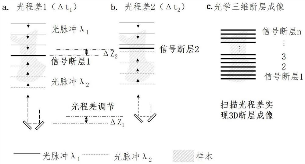
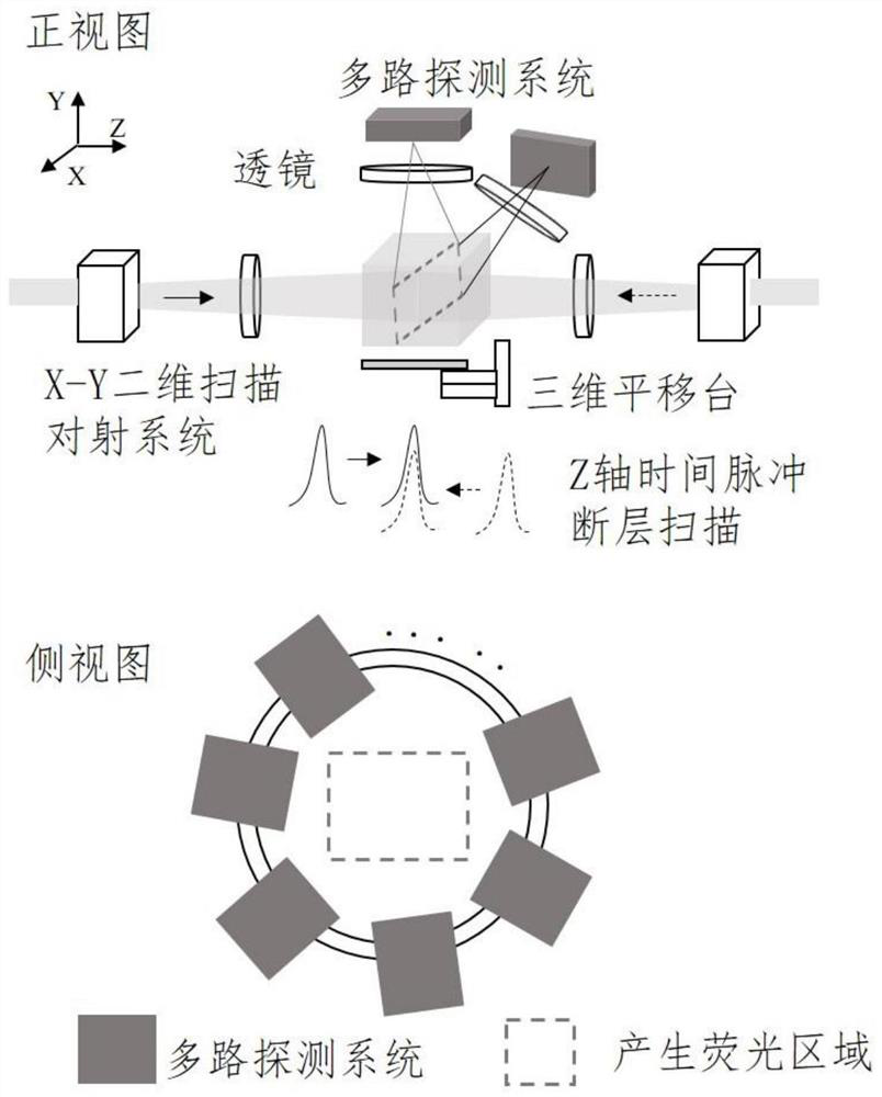
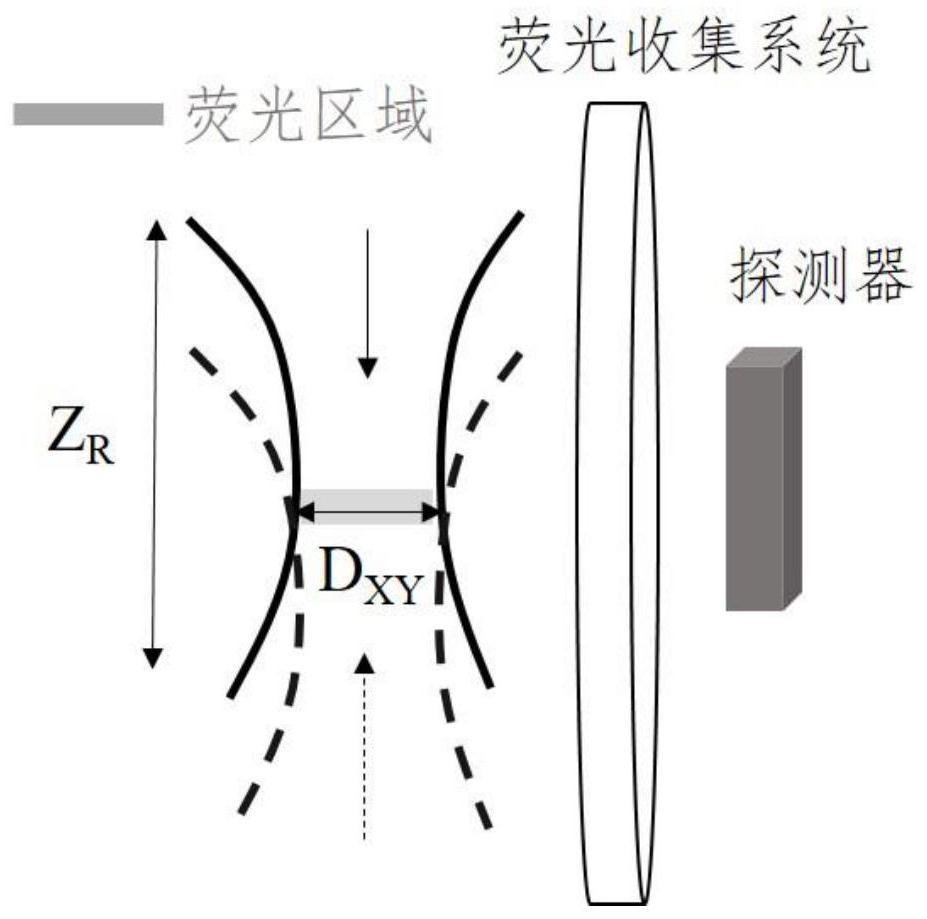
[0038] Pulsed laser has the advantages of ultra-short pulse and high repetition rate. Taking femtosecond light source as an example, the laser outputs two beams of synchronous light source. The thickness of the sheet; the thickness of the time light sheet or the Z-axis resolution of imaging is determined by the time pulse width of the two beams of light pulses. Pulse light sources include attosecond, femtosecond, picosecond, and nanosecond pulse lasers. Reducing the time pulse width can achieve Higher axial resolution. The repetition frequency of t...
Embodiment 2
[0054] Example 2 Vascular Imaging
[0055] The difference between this embodiment and the first embodiment is that it adopts the certified ICG dye that can be used on the human body. Its absorption peak is at 800 nm, and it can be excited by ~1300 nm and ~2100 nm in the second near-infrared region, and the excitation light has a deeper The penetration depth of a single beam of light cannot excite fluorescence, and only a time light sheet signal is generated where the two beams of light overlap to achieve tomographic imaging of blood vessels, such as Figure 5 shown;
[0056] The sample is processed by fluorescence, phosphorescence, Raman, photothermal, and photoacoustic labeling. The two pulsed light sources alone cannot excite the labeling group to send a signal, and only when the two pulsed light sources act together can the signal be generated.
Embodiment 3
[0057] Example 3 SRS or CARS imaging of fat and protein
[0058] The difference between this embodiment and Embodiment 1 is that the sample is not fluorescently labeled, and the two light pulses λ 1 , lambda 2 Exciting endogenous molecules in the sample to emit signals when they coincide simultaneously in space and time, said signals include optical, acoustic, thermal, electrical, magnetic signals. The laser chooses pump light and Stokes light.
[0059] The specific implementation process of SRS: select the wavelength of the pump light and the Stokes light to excite specific analytical chemical bonds, modulate the Stokes light through the acousto-optic modulator, and output the reference signal of the modulator to the lock-in amplifier ; After a suitable time delay, then coincide with the pump light on the sample, and use a high-pass low-reflection dichroic mirror to reflect the pump light to the photodiode for detection on the optical path of the forward propagation of the ...
PUM
| Property | Measurement | Unit |
|---|---|---|
| thickness | aaaaa | aaaaa |
Abstract
Description
Claims
Application Information
 - R&D
- Intellectual Property
- Life Sciences
- Materials
- Tech Scout
- Unparalleled Data Quality
- Higher Quality Content
- 60% Fewer Hallucinations
Browse by: Latest US Patents, China's latest patents, Technical Efficacy Thesaurus, Application Domain, Technology Topic, Popular Technical Reports.
© 2025 PatSnap. All rights reserved.Legal|Privacy policy|Modern Slavery Act Transparency Statement|Sitemap|About US| Contact US: help@patsnap.com


