Spent fuel rod hot cell cutting device

A cutting device and spent fuel technology, applied in positioning devices, feeding devices, clamping, etc., can solve the problems of large radioactive waste liquid, increased dose rate, increased difficulty in decontamination of hot cells, and waste liquid disposal expenses. To achieve the effect of reducing pollution and reducing production

Pending Publication Date: 2020-01-14
CHINA INSTITUTE OF ATOMIC ENERGY
View PDF0 Cites 6 Cited by
  • Summary
  • Abstract
  • Description
  • Claims
  • Application Information

AI Technical Summary

Problems solved by technology

This method will not only generate a large amount of radioactive waste liquid, but also the highly radioactive cuttings and aerosols produced by cutting cannot be effectively collected, resulting in an increase in the overall dose rate in the hot chamber, which will not only affect the maintenance of the equipment in the hot chamber, but also increase the temperature of the hot chamber. The difficulty of decontamination and the cost of waste liquid disposal
[0004] The commonly used method of cutting spent fuel rods is to use a pipe cutter to cut spent fuel rods. Although the pipe cutter can collect the chips and aerosols generated during the cutting process, due to the functional limitations of the pipe cutter itself , the pipe cutter cutting inevitably needs to cut the fuel pellets together with the fuel cladding, which increases the production of radioactive pollutants and the pipe cutter has a size range, and can only cut certain sizes of spent fuel rods

Method used


Image

  • Spent fuel rod hot cell cutting device
  • Spent fuel rod hot cell cutting device
  • Spent fuel rod hot cell cutting device

Examples


Embodiment Construction

[0027] The specific implementation manner of the invention will be described below in conjunction with the accompanying drawings.

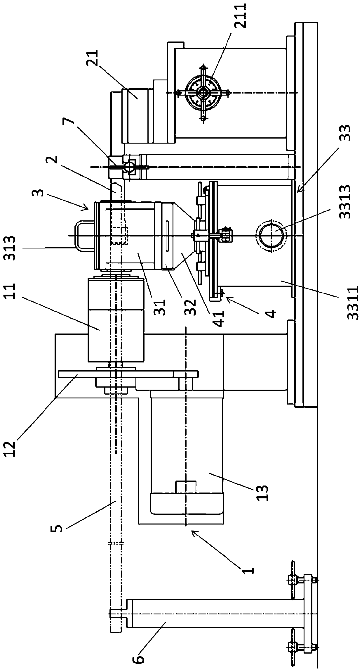
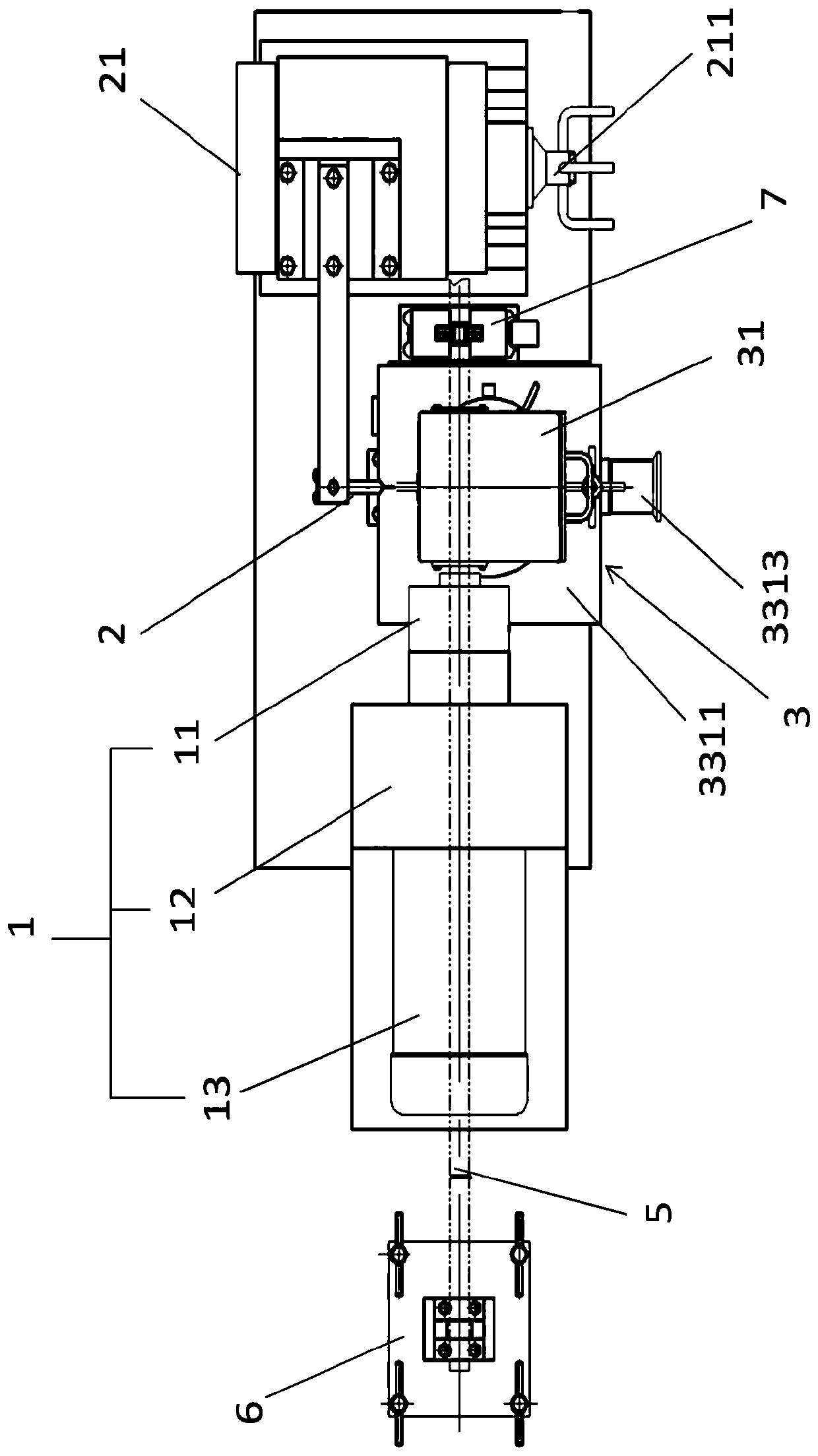
[0028] Such as figure 1 with figure 2 As shown, the spent fuel rod thermal cell cutting device according to the embodiment of the present invention includes a clamping assembly 1 for clamping a spent fuel rod 5 and a cutting tool 2 for cutting a spent fuel rod 5, the spent fuel rod thermal cell The cutting device also includes a cutting tool box 3, the cutting tool 2 is arranged in the cutting tool box 3, and the larger chips generated in the cutting process are collected in the cutting tool box 3, and the cutting tool box 3 also includes a suction filter assembly 33, The suction filter assembly 33 is used for suction filtering the aerosol generated during the cutting process.

[0029] The clamping assembly 1 of the spent fuel rod hot cell cutting device of the present invention includes a clamping part 11, a transmission device 12 and a motor ...


PUM


Abstract

The embodiment of the invention discloses a spent fuel rod hot cell cutting device. The spent fuel rod hot cell cutting device comprises a clamping assembly used for clamping a spent fuel rod and a cutting tool used for cutting the spent fuel rod, wherein the cutting tool is arranged in a cutting tool box, cuttings generated in the cutting process are collected in the cutting tool box, and the cutting tool box further comprises a suction and filtering assembly used for sucking and filtering aerosol generated in the cutting process. According to the embodiment of the spent fuel rod hot cell cutting device, the spent fuel rods of different sizes can be cut according to different processes, radioactive waste can be effectively collected and absorbed, and the pollution of the spent fuel rod cutting process to a hot cell is reduced.

Description

technical field [0001] The invention relates to the field of fuel rod cutting equipment, in particular to a spent fuel rod hot cell cutting device. Background technique: [0002] In current nuclear reactors, nuclear fuel rods are the source of maintaining the fission chain reaction in the reactor core, which transfers the energy generated by fission to the coolant in the form of heat through the cladding, and is one of the most critical components in the reactor. After the nuclear fuel rods react to a certain burnup depth, the reaction efficiency of the fission chain reaction will be affected. At this time, the nuclear fuel rods need to be unloaded from the reactor. The unloaded nuclear fuel rods are spent fuel rods, which have extremely high radioactivity At the same time, there are also a large amount of unused value-added materials, such as 238U or 232Th, so it is necessary to process the spent fuel rods to extract the nuclides. During the processing of the spent fuel rod...

Claims


Application Information

Patent Timeline
Patent Type & Authority Applications(China)
IPC IPC(8): B23D79/00B23Q11/00B23Q5/22B23Q3/06B23Q1/76B01D53/02B01D46/00
CPCB01D46/00B01D53/02B23D79/00B23Q1/76B23Q1/763B23Q3/064B23Q5/22B23Q11/00B23Q11/0067
Inventor 卞伟彭顺米刘立明王鑫解含黄英郭丽娜韩华钱进李显华王文安
Owner CHINA INSTITUTE OF ATOMIC ENERGY
Why Eureka
Try Eureka