
Heat exchange system

A technology of heat exchange system and heat exchange tube, which is applied in the field of heat exchange system, can solve the problems such as the gap between the fin and the heat exchanger, the reduction of the area of ​​the air flow channel, and the limited size of the air flow channel, so as to ensure the heat exchange performance, Improve the heat transfer efficiency and eliminate the effect of heat transfer temperature difference

Pending Publication Date: 2019-12-24
SANHUA HANGZHOU MICRO CHANNEL HEAT EXCHANGER
View PDF12 Cites 1 Cited by
  • Summary
  • Abstract
  • Description
  • Claims
  • Application Information

AI Technical Summary

Problems solved by technology

[0003] However, there is a heat transfer temperature difference between the heat exchange tube and the fins, and the heat exchange efficiency will be lost. After the heat exchanger is used for a long time, there will be a gap at the connection between the fins and the heat exchanger, resulting in a decrease in heat exchange efficiency.
[0004] In addition, the size of the airflow channel between adjacent fins is limited. When the surface of the heat exchanger is frosted, the frost layer on the surface of the fins will become thicker and thicker with time, gradually blocking the air flow gap. , the heat transfer performance continues to decline. After entering the defrosting condition, the area of ​​the air flow channel decreases, which affects the heat transfer efficiency

Method used


Image

  • Heat exchange system
  • Heat exchange system
  • Heat exchange system

Examples


Embodiment Construction

[0050] Embodiments of the present invention are described in detail below, examples of which are shown in the drawings, wherein the same or similar reference numerals designate the same or similar elements or elements having the same or similar functions throughout. The embodiments described below by referring to the figures are exemplary only for explaining the present invention and should not be construed as limiting the present invention.

[0051] In describing the present invention, it should be understood that the terms "length", "width", "thickness", "upper", "lower", "front", "rear", "left", "right", " The orientation or positional relationship indicated by "vertical", "horizontal", "top", "bottom", "axial", "radial" and "circumferential" are based on the orientation or positional relationship shown in the drawings, only It is for the convenience of describing the present invention and simplifying the description, but does not indicate or imply that the referred device ...


PUM


Abstract

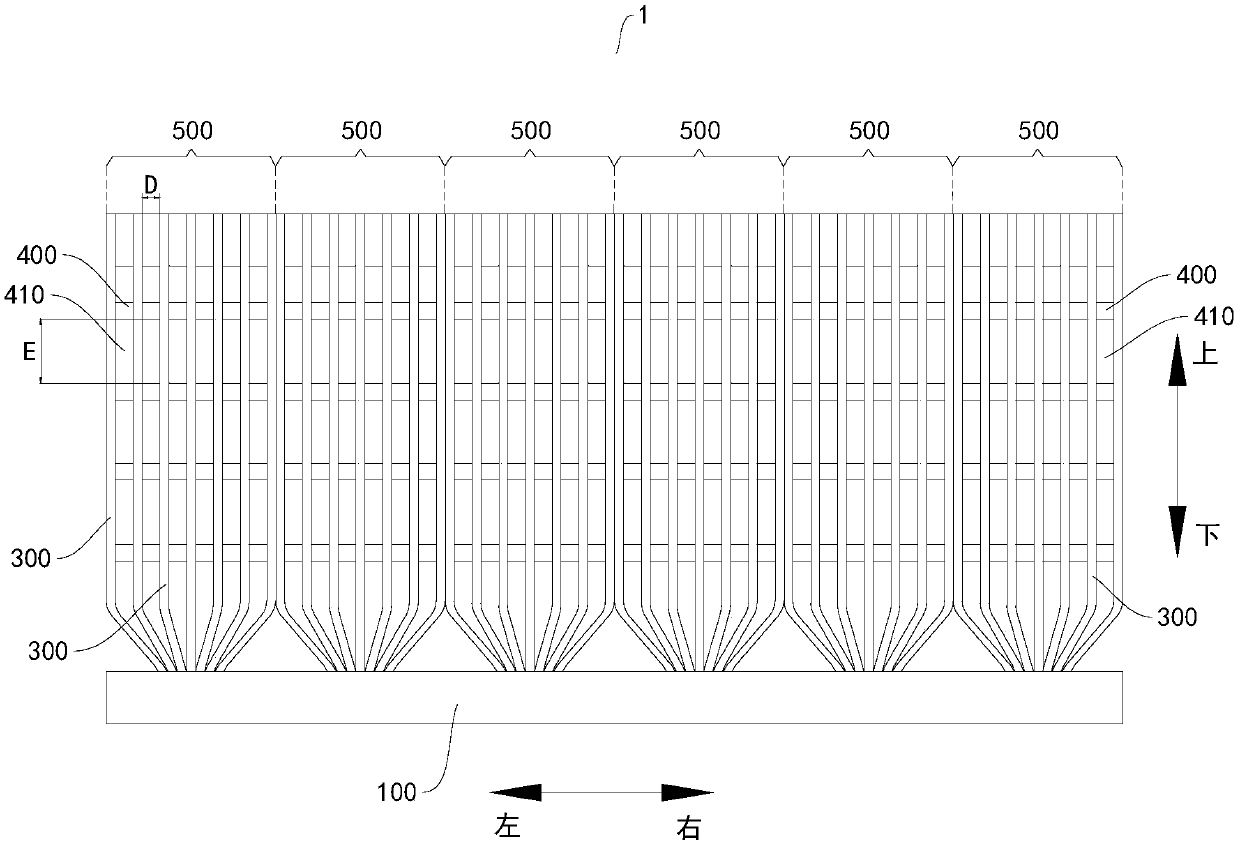
The invention discloses a heat exchange system which comprises at least one heat exchanger. The heat exchanger comprises a first collecting pipe and a second collecting pipe, multiple heat exchange pipes used for circulation of a first heat exchange medium and spacing parts, wherein two ends of each of heat exchange pipes are connected to the first collecting pipe and the second collecting pipe respectively, each of the heat exchange pipes comprises at least three straight sections and at least two bent sections, the multiple heat exchange pipes are arranged to form multiple heat exchange units, and the straight sections of each of the heat exchange pipes of the same heat exchange unit are mutually parallel; each of the spacing parts is disposed between the adjacent heat exchange pipes ofthe same heat exchange unit, the spacing part between the adjacent heat exchange pipes are disposed at an interval along the length direction of the heat exchange pipes and thus a through hole is formed; and a flow direction of a second heat exchange medium which passes through the through hole is not parallel with the straight sections, so the second heat exchange medium successively flows through the different straight sections of each of the heat exchange pipes. The heat exchange system disclosed by the embodiment of the invention is characterized in that heat exchange is mainly realized bythe heat exchange pipes and has the beneficial effects that heat exchange efficiency is high; heat exchange capability is high, etc.

Description

technical field [0001] The invention relates to the technical field of heat exchange, in particular to a heat exchange system. Background technique [0002] In the field of air conditioning and refrigeration, the commonly used air heat exchanger is a copper tube fin heat exchanger. The main components of the heat exchanger include circular heat exchange tubes and flat fins interspersed on the heat exchange tubes. The refrigerant mainly exchanges heat through the fins. [0003] However, there is a heat transfer temperature difference between the heat exchange tube and the fin, and the heat exchange efficiency will be lost. After the heat exchanger is used for a long time, a gap will be formed at the connection between the fin and the heat exchanger, resulting in a decrease in heat exchange efficiency. [0004] In addition, the size of the airflow channel between adjacent fins is limited. When the surface of the heat exchanger is frosted, the frost layer on the surface of the...

Claims


Application Information

Patent Timeline
Patent Type & Authority Applications(China)
IPC IPC(8): F25B39/00F24F13/30
CPCF25B39/00F24F13/30
Inventor 蒋建龙赵磊钟笑鸣
Owner SANHUA HANGZHOU MICRO CHANNEL HEAT EXCHANGER
Learn More