
Laser-enhanced three-dimensional micro-region electro-deposition method and corresponding device thereof

An electrodeposition device and electrodeposition technology, applied in the field of electrodeposition, can solve the problems of low deposition rate, extremely high relative displacement accuracy, and increased system cost

Inactive Publication Date: 2019-12-13
橙河微系统科技(上海)有限公司
View PDF5 Cites 13 Cited by
  • Summary
  • Abstract
  • Description
  • Claims
  • Application Information

AI Technical Summary

Problems solved by technology

However, the deposition rate of this microtube-based micro-area electrodeposition technology is low, usually less than 0.1 μm / s, which limits its application; moreover, the too low deposition rate also leads to the control of the distance between the nozzle and the sample when the system is working. And the relative displacement accuracy is extremely high, so the displacement control mostly uses piezoelectric displacement stages with high precision (such as displacement accuracy better than 1nm), which increases the system cost

Method used


Image

  • Laser-enhanced three-dimensional micro-region electro-deposition method and corresponding device thereof
  • Laser-enhanced three-dimensional micro-region electro-deposition method and corresponding device thereof
  • Laser-enhanced three-dimensional micro-region electro-deposition method and corresponding device thereof

Examples


specific Embodiment 1

[0067] In this embodiment, an application of the present invention is described by taking electrodeposition of copper nanowires along the X direction as an example.

[0068] Electrolyte is CuSO 4 ·5H 2 For a uniform aqueous solution of O, the molar concentration of the solute is between 0.01-1M according to the requirements of the size and rate of the deposited nanowires. The capillary (outer diameter 1 mm, inner diameter 0.5 mm) was sharpened by a commercial needle puller, and the outer diameter of the capillary tip was about 1 μm after treatment. The 10mL glass syringe was filled with electrolyte, and the syringe was connected to the capillary through an adapter, and the electrolyte tube in the syringe was injected into the capillary through a syringe pump, and micro-droplets appeared at the tip of the stretching section of the capillary. The samples were heavily doped silicon wafers without oxide layer, and the silicon wafers were rinsed with hydrofluoric acid before elec...

specific Embodiment 2

[0070] In this embodiment, the application of the present invention in vertical nanowire growth is illustrated by taking electrodeposition of copper nanowires along the direction perpendicular to the sample surface as an example.

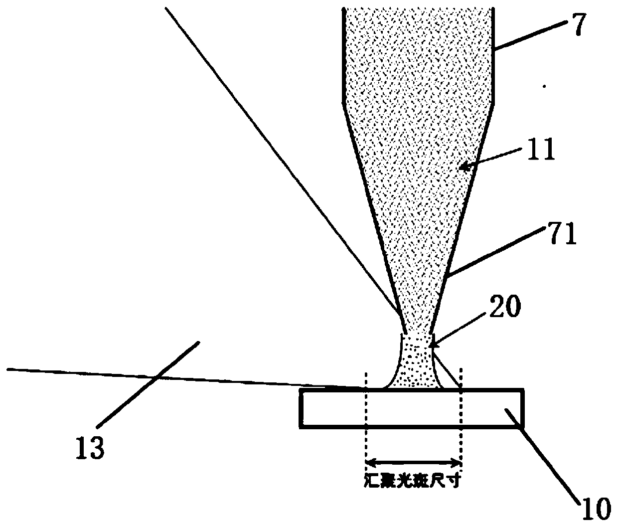
[0071] The reagents, materials and system configuration used are the same as those in Example 1. Before the approaching operation, the adjusted and converged laser spot is irradiated on the contact surface between the droplet 20 at the tip of the capillary and the surface of the sample 10 . Then, according to embodiment 1, the capillary is approached to the sample surface under the positive bias of the copper wire until the ammeter detects an appreciable number ( Figure 4 a). The electrodeposition process begins, and the copper layer is deposited on the sample surface, forming deposited copper 21 ( Figure 4 b). Subsequently, the computer controls the Z-direction electric control platform to move slowly along the vertical direction of the sample...


PUM

PropertyMeasurementUnit
diameteraaaaaaaaaa

Abstract

The invention provides a laser-enhanced three-dimensional micro-region electro-deposition method. the method integrates laser irradiation into a microtubule-based micro-region electro-deposition device to obtain an improved deposition rate. Electrolyte is poured into an electrolyte chamber and a microtubule, a tip of the microtubule is close to a sample surface by the regulation of a translation stage, a droplet at the tip of the microtubule forms a meniscus on the sample surface so that the diffusion of the droplet on the sample surface is limited, and machining accuracy of electro-depositionis beneficially controlled. As the electrolyte in the microtubule is connected with the positive potential and the surface of a conductive sample is the negative potential, the electro-deposition process can occur. The laser is irradiated on the contact surface between the droplet and the sample, and a laser thermal effect improves the electron transfer efficiency in the electrolyte, acceleratesthe positive shift of the electrochemical balance potential and causes local eddy current stirring in the droplet, and therefore accelerates the electro-deposition process. According to the preset pattern, the electronic control transition stage movement is regulated, so the three-dimensional relative movement of the microtubule and the sample surface is realized.

Description

technical field [0001] The invention relates to the technical field of electrodeposition, in particular to a laser-enhanced three-dimensional micro-region electrodeposition method, and the invention also provides a device using the method. Background technique [0002] Electrodeposition technology is a common coating processing technology in industrial production. Its work is based on electrochemical principles. The sample is immersed in a specific electrolyte as a cathode. Metal ions in the electrolyte gather on the surface of the sample and undergo a reduction reaction. Thereby forming a metal coating layer on the surface of the sample. Electrodeposition technology has been widely used in electronic information, anti-corrosion, modification and other fields. However, the processing precision of the existing electrodeposition technology is low, and the processing resolution is only about 100 μm. In order to improve the processing accuracy of electrodeposition technology, ...

Claims


Application Information

Patent Timeline
Patent Type & Authority Applications(China)
IPC IPC(8): C25D5/02C25D5/08C25D17/00
CPCC25D5/024C25D5/08C25D17/00
Inventor 朱国栋龚大卫
Owner 橙河微系统科技(上海)有限公司
Learn More