
Frequency locking system and method based on Rydberg electromagnetic induction transparent signal

An electromagnetic induction transparent and signal technology, applied in circuits, electrical components, laser parts, etc., can solve the problems of laser line width widening, perturbation, and unsuitability for portable systems, and achieves stable laser frequency, low environmental requirements, simple structure

Active Publication Date: 2019-11-01
UNIVERSITY OF CHINESE ACADEMY OF SCIENCES +1
View PDF8 Cites 3 Cited by
  • Summary
  • Abstract
  • Description
  • Claims
  • Application Information

AI Technical Summary

Problems solved by technology

People have developed various frequency locking methods, such as locking the laser frequency on an ultrastable cavity [Appl.Phys.B 31, 97-105 (1983)]. The advantage of this method is that the linewidth of the laser can be narrowed to Surprising order of magnitude, mHz, but this method has extremely high requirements on the environment, such as mechanical stability and temperature stability, and is not suitable for the development of portable systems
Another method is Adams [Appl.Phys.Lett.94 071107 (2009)] et al. developed the use of EOM to modulate the frequency of the probe light to obtain the error signal of the EIT, and then lock the frequency of the coupled light in the intermediate state and Rydberg The advantage of this method is that the laser frequency will be absolutely accurate, but it needs to introduce EOM optical path and servo system in the experiment, which increases the complexity of the system; on the basis of Adams et al., Zhao Jianming et al. [Chin.Phys .B 25, 053201(2016)] Utilize the frequency of current modulation to obtain the error signal of the EIT error signal frequency-locked. Although this method does not require a complicated optical path, the modulation signal is added to the laser diode current, so it will Causes broadening and perturbation of the laser linewidth

Method used


Image

  • Frequency locking system and method based on Rydberg electromagnetic induction transparent signal
  • Frequency locking system and method based on Rydberg electromagnetic induction transparent signal
  • Frequency locking system and method based on Rydberg electromagnetic induction transparent signal

Examples


Embodiment Construction

[0031] The present invention will be further described below in combination with specific embodiments.

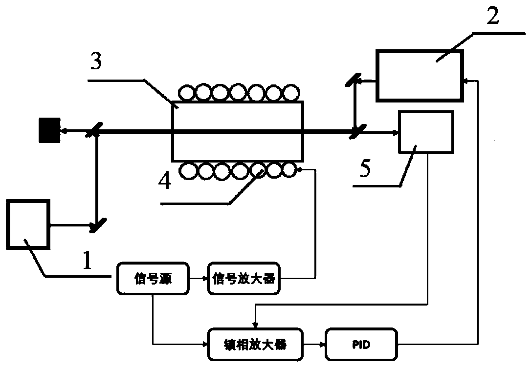
[0032] A frequency locking system based on Rydberg electromagnetic induction transparent signal, such as figure 1 As shown, the system includes a detection light source 1, a coupling light source 2, a rubidium vapor pool 3, a photodetector 5, a sinusoidal signal source, a signal amplifier, a lock-in amplifier and a proportional-integral-derivative (PID) controller; The light source 1 and the coupling light source 2 are relatively arranged at both ends of the rubidium vapor pool 3, and the probe light and coupling light are relatively transmitted through the rubidium vapor pool and are strictly overlapped; the rubidium vapor pool 3 is a cylindrical glass tube filled with After rubidium vapor is added, the intensity of the probe light is about 30 microwatts, the spot diameter is about 1 mm, and the polarization is left-handed. The light intensity of the coupled light is abou...


PUM


Abstract

The invention discloses a frequency locking system and method based on the Rydberg electromagnetic induction transparent signal. The system includes a probe light source, a coupling light source, a rubidium vapor cell, a photodetector, a sinusoidal signal source, a signal amplifier, a lock-in amplifier and a proportional-integral-integral controller; and the frequency locking method uses a coupledlight source to scan the frequency of the coupled light passing through the rubidium vapor cell to obtain a Rydberg electromagnetic induction transparent signal, and adopts an alternating magnetic field to modulate the atomic energy level to achieve the frequency modulation of the Rydberg electromagnetic induction transparent signal so as to obtain the differential signal of the Rydberg electromagnetic induction transparent signal, namely the error signals required by frequency locking, and the frequency locking for the coupled light laser is performed. The system and method provided by the invention are wide in application range, narrow in line width, simple and stable in structure, low in environmental requirement and low in cost, and are suitable for development of portable systems.

Description

technical field [0001] The invention relates to the field of laser frequency locking, in particular to a frequency locking system and method based on Rydberg electromagnetic induction transparent signals. Background technique [0002] Due to its large electric dipole moment, Rydberg atoms have great application prospects in quantum storage, quantum computing, and quantum simulation. The step-type electromagnetic induction transparency based on Rydberg atoms has been widely studied. In recent years, the microwave electric field meter based on the electromagnetic induction transparency of Rydberg atoms has provided a quantum benchmark for the measurement of microwave electric fields [Nature Physics, 8, 819 -824(2012)], has received people's attention, and how to make the microwave electric field meter portable is one of the research hotspots that people pay attention to. Locking the laser frequency on the transition line between the intermediate state and the Rydberg state is...

Claims


Application Information

Patent Timeline
Patent Type & Authority Applications(China)
IPC IPC(8): H01S5/0687
CPCH01S5/0687
Inventor 贾凤东谢锋张剑张磊王飞钟志萍
Owner UNIVERSITY OF CHINESE ACADEMY OF SCIENCES
Learn More