
Microfluidic chip, microfluidic system and infrared microfluidic analysis method

A microfluidic chip and microfluidic system technology, applied in the field of microfluidics, can solve problems such as difficult to meet the size, unable to control the temperature of the liquid pool, unable to exchange and circulate the liquid, etc., to achieve easy calibration, shorten the vertical height, and avoid errors the effect of existence

Active Publication Date: 2019-12-24
SHANGHAI ADVANCED RES INST CHINESE ACADEMY OF SCI
View PDF10 Cites 0 Cited by
  • Summary
  • Abstract
  • Description
  • Claims
  • Application Information

AI Technical Summary

Problems solved by technology

[0004] In view of the shortcomings of the prior art described above, the purpose of the present invention is to provide a microfluidic chip, a microfluidic system and an infrared microfluidic analysis method, which are used to solve the problem of using Fourier transform infrared microscopy in the prior art. Method research When using a liquid pool for liquid research, it is difficult to accurately deduct and correct the influence of the liquid. The liquid in the pool cannot be exchanged and circulated, and it cannot provide a precise and controllable liquid environment. It cannot control the temperature and the size of the traditional liquid pool is difficult. Meet the small working distance requirements of infrared microscopes and other issues

Method used


Image

  • Microfluidic chip, microfluidic system and infrared microfluidic analysis method
  • Microfluidic chip, microfluidic system and infrared microfluidic analysis method
  • Microfluidic chip, microfluidic system and infrared microfluidic analysis method

Examples


Embodiment 1

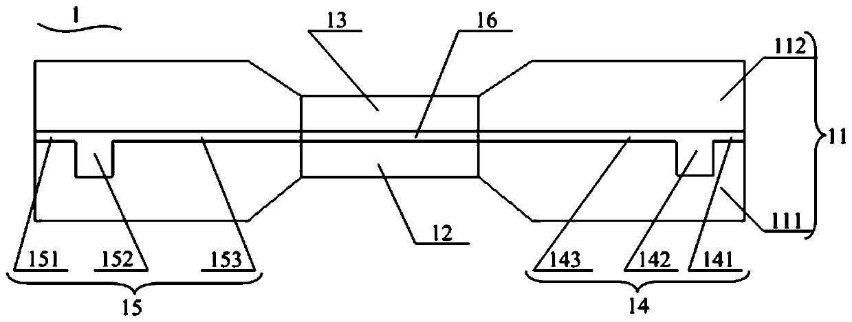
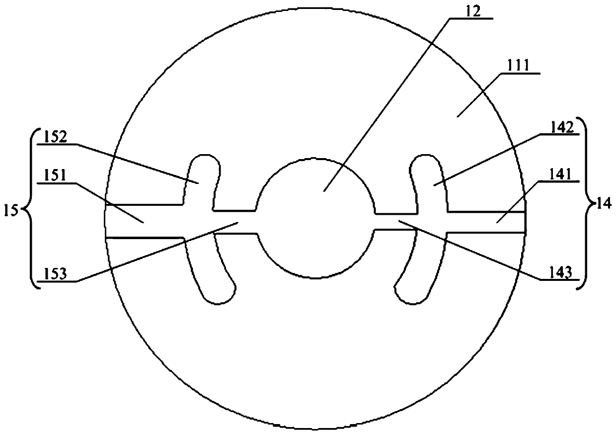
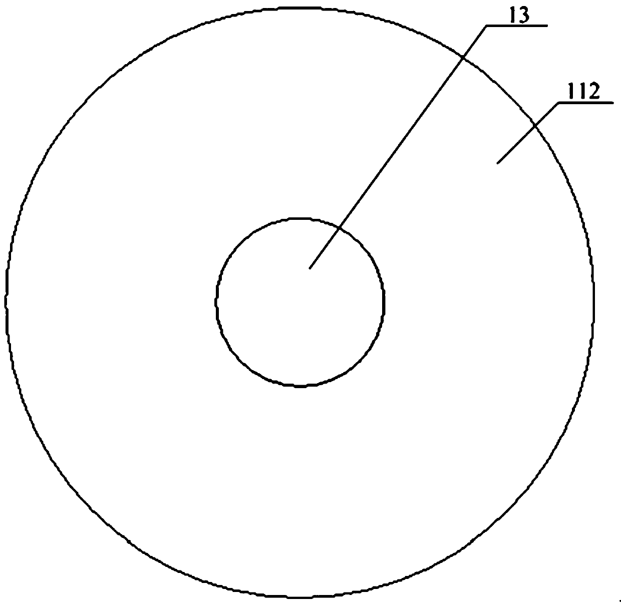
[0106] see figure 1 , the present invention provides a microfluidic chip 1, the microfluidic chip 1 includes: a frame structure 11; a first window 12, the first window 12 is embedded in the frame structure 11; A window 12 can comprise an infrared transparent window or an infrared reflective window; a second window 13, the second window 13 can be embedded in the frame structure 11, and the second window 13 and the There is a gap between the first windows 12 to form a sample chamber 16 between the second windows 13 and the first windows 12; the second windows 13 may include infrared transparent windows; Liquid inlet channel 14, the liquid inlet channel 14 is located in the frame structure 11, one end of the liquid inlet channel 14 communicates with the sample chamber 16, and the other end extends to the surface of the frame structure 11 The liquid outlet flow channel 15, the liquid outlet flow channel 15 is located in the frame structure 11, one end of the liquid outlet flow ch...

Embodiment 2

[0127] Please combine Figure 1 to Figure 3 refer to Figure 4 and Figure 5 , the present invention also provides a microfluidic system, the microfluidic system includes: the microfluidic chip 1 as described in the first embodiment, the specific structure of the microfluidic chip 1 please refer to the first embodiment, No longer repeat here; supply device 2, described supply device 2 is connected with described liquid inlet channel 14 and described liquid outlet channel 15, and described supply device 2 is used for providing in described sample chamber 16 Liquid to be detected (for example, water), sample suspension (for example, cell suspension) or carrier liquid, the carrier liquid provides a living environment or liquid environment for the sample to be detected located in the sample chamber; temperature control device 3, The temperature control device 3 is used to place the microfluidic chip 1 and heat the liquid to be tested, the sample suspension or the carrier liquid ...

example 1

[0143] In this example, as Figure 4 As shown, the supply device 2 includes an injection device 20 with injection function, the liquid inlet pipeline 21, the injection device 22 with extraction function and the liquid outlet pipeline 23; The device 20 includes a syringe pump or a syringe, and the liquid inlet pipeline 21 and the liquid outlet pipeline 23 are silicone pipelines; the microfluidic chip 1 is connected to the supply device 2 in the following manner: the microfluidic chip 1 The liquid inlet channel 141 in the liquid inlet channel 14 of the fluidic chip 1 is connected to the syringe in the syringe pump 20 with an injection function via a pipe joint and a silicone tube. The liquid outlet channel 151 of the liquid outlet channel 15 in the fluidic chip 1 is connected to the syringe in the syringe pump 22 via a pipe joint and a silicone pipeline; The microfluidic chip 1 is connected to the temperature control device 3 in the following manner: the microfluidic chip 1 is ...


PUM

PropertyMeasurementUnit
thicknessaaaaaaaaaa
thicknessaaaaaaaaaa
thicknessaaaaaaaaaa

Abstract

The invention provides a micro-fluidic chip, a micro-fluidic system and an infrared micro-fluidic analysis method. The micro-fluidic system comprises: a micro-fluidic chip; a supply device connected with the liquid inlet flow channel and the liquid outlet flow channel and used for providing detection liquid, sample suspension liquid or carrier liquid for the sample chamber, wherein the carrier liquid provides a living environment or a liquid environment for a to-be-detected sample located in the sample chamber; and a temperature control device which is used for placing the micro-fluidic chip and heating the to-be-detected liquid, the sample suspension or the carrier liquid in the micro-fluidic chip. Injection, outflow and circulation of to-be-detected liquid, sample suspension or carrier liquid can be accurately controlled through the supply device and the micro-fluidic chip, a precise and controllable liquid environment can be provided, and the micro-fluidic chip can be used for researching liquid-containing water systems such as living cells and water-containing materials.

Description

technical field [0001] The invention belongs to the field of microfluidic technology, in particular to a microfluidic chip, a microfluidic system and an infrared microfluidic analysis method. Background technique [0002] Fourier Transform Infrared Spectroscopy (FTIR) is a powerful means to characterize the composition and structure of matter, and is widely used in chemistry, materials, medicine, life sciences and other fields. The infrared microspectroscopy technology combining infrared spectrometer and infrared microscope can observe the morphology and chemical composition of the sample, and can detect the two-dimensional spatial distribution of the sample components, and carry out spatially resolved microscopic research. Synchrotron radiation infrared microscopy is a technique that combines synchrotron radiation infrared light sources with traditional Fourier transform infrared microscopy. Synchrotron radiation infrared light not only covers the far-infrared, mid-infrare...

Claims


Application Information

Patent Timeline
Patent Type & Authority Patents(China)
IPC IPC(8): B01L3/00G01N21/3577
CPCB01L3/5027B01L3/502707B01L3/50273B01L2200/027B01L2200/10B01L2300/0835B01L2300/12B01L2300/1805G01N21/3577
Inventor 周晓洁钟佳佳常超唐雨钊
Owner SHANGHAI ADVANCED RES INST CHINESE ACADEMY OF SCI
Learn More