
Arsenic alkali slag resource utilization device and method thereof

A technology for recycling arsenic-alkali slag, which is applied in the field of resource utilization equipment for arsenic-alkali slag. The effect of power consumption

Pending Publication Date: 2019-08-20
长沙紫宸科技开发有限公司
View PDF4 Cites 6 Cited by
  • Summary
  • Abstract
  • Description
  • Claims
  • Application Information

AI Technical Summary

Problems solved by technology

The problem that this pyroprocessing method exists is, one, the product is highly arsenic-containing " antimony-arsenic-lead alloy " and the toxic scum of trisodium phosphate containing arsenic, and the market of the antimony-arsenic-lead alloy with extremely unstable composition, The follow-up treatment of toxic scum containing trisodium phosphate and arsenic is also a difficult problem; second, it is a typical intermittent heat treatment process with less processing capacity; The volatilization of flue gas also has a serious pollution risk; moreover, the energy consumption is high, and the potential pollution hazard is great, especially the arsenic-containing trisodium phosphate scum can easily flow into the agricultural fertilizer market to spread pollution
Third, the treatment of arsenate that does not contain a large amount of antimonate is smelted with carbon as a reducing agent. When the reduction temperature is lower than 700°C, the reducing ability is extremely weak, and only when the temperature is above 700°C will it show better reducibility with the increase of temperature ; while using carbon as a reducing agent to smelt arsenic-alkali slag, the overall reducing ability is still extremely weak when the reducing temperature is lower than 800°C, and the reduction will be better when the temperature is above 900°C. The higher the treatment temperature for hazardous waste, not only The problem of high energy consumption and higher equipment requirements has a greater potential risk of accidents; moreover, this closed reduction furnace adopts an intermittent process in which the vacuum pump continues to evacuate for several hours, so the energy consumption is too high and the processing capacity is small; Fourth, arsenic Steam or arsenic fume or elemental arsenic is easily oxidized, especially during the process of forcibly extracting from the high temperature furnace with a vacuum pump to cooling, the reducing atmosphere used is a mixed atmosphere of inert gas and / or nitrogen, hydrogen and / or carbon monoxide, etc. Extremely difficult to recycle, or lead to poor economy or pollute the atmosphere
Fifth, the vacuum pump that this method relies on for vacuuming arsenic flue gas has extremely poor adaptability to metal particles or flue gas dust, making it difficult to ensure normal production and operation
[0020] In summary, it is difficult to separate arsenic, antimony, and alkali resources in the existing treatment processes for various types of arsenic-alkali slag, especially the disposal of arsenic is difficult, and problems such as environmental protection and economic efficiency are prominent
[0021] At present, regardless of the pyro-reduction treatment of arsenic-alkali slag or the production of metallic arsenic, the reduction reaction of arsenic-alkali slag, arsenic oxide, or arsenic-containing ore is generally carried out with carbon or hydrogen as a reducing agent. Practice or Research Reports of Using Ammonia as Efficient Reductant for Direct Injection Reduction or Boiling Reduction

Method used


Image

  • Arsenic alkali slag resource utilization device and method thereof
  • Arsenic alkali slag resource utilization device and method thereof

Examples


Embodiment 1

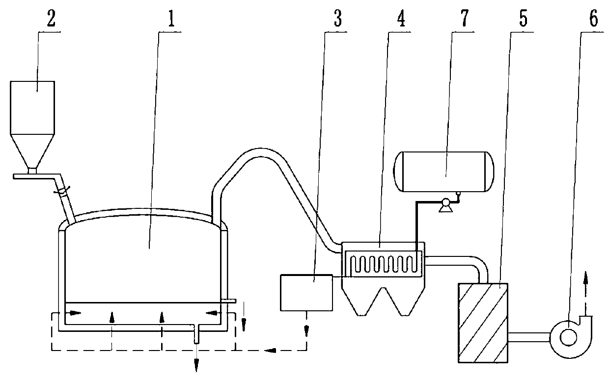
[0057] as attached figure 1 As shown, the device for resource utilization of arsenic-alkali slag in this embodiment mainly includes: electric heating reduction furnace (1), powder lock air meter feeding device (2), ammonia injection device (3), cooling (heat exchange) device (4), residual ammonia finishing device (5), centrifugal fan (6), ammonia storage device (7), the discharge port of the powder lock air meter feeding device (2) and the electrothermal reduction furnace (1 ), the ammonia injection device (3) is connected with the electrothermal reduction furnace (1), the cooling (heat exchanger) (4) with the ammonia gas delivery pipeline, and the cooling (heat exchanger) (4) is respectively connected with the electric heating The exhaust outlet of the reduction furnace (1) and the inlet of the residual ammonia finishing device (5) are connected by pipes, the waste gas outlet of the residual ammonia finishing device (5) is connected with the air inlet of the centrifugal fan (...

Embodiment 2

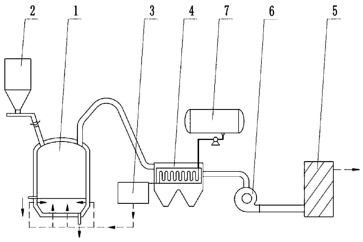
[0066]as attached figure 2 As shown, the device for resource utilization of arsenic-alkali slag in this embodiment mainly includes: electric heating reduction furnace (1), powder lock air meter feeding device (2), ammonia injection device (3), cooling (heat exchange) device (4), residual ammonia finishing device (5), centrifugal fan (6), ammonia storage device (7), the discharge port of the powder lock air meter feeding device (2) and the electrothermal reduction furnace (1 ), the ammonia injection device (3) is connected with the electrothermal reduction furnace (1) and the cooling (heat exchanger) (4) respectively with the ammonia gas delivery pipeline, and the inlet of the cooling (heat exchanger) (4) is connected with The exhaust outlet of the electrothermal reduction furnace (1) is connected, the centrifugal fan (6) is connected with the exhaust gas outlet of the cooling (heat exchanger) (4) and the inlet of the residual ammonia finishing device (5) by pipelines, and the...

Embodiment 3

[0074] The device for recycling the arsenic-alkali slag in this embodiment is the same as that in Embodiment 1.

[0075] The arsenic-alkali slag produced by an antimony smelter was selected as the raw material, and the chemical composition (average value) of the raw material was: As: 22.92%,

[0076] Sb: 34.85%, Pb 3.27%, Na: 27.78%, arsenic-alkali slag plus 15% by mass of rice husk pre-grinded into a 160-mesh sieve with 5% of the remaining powder; commercially available liquid ammonia was selected as the reducing agent; in the test Device line test.

[0077] The method for resource utilization of arsenic-alkali slag in this embodiment includes the following steps: liquid ammonia is vaporized by a heat exchange device and the temperature is raised to 250°C. The arsenic-alkali slag powder material preheated to 350°C±10°C is continuously fed into the electrothermal reduction furnace at 800°C±10°C, and the bottom spray method is used to directly inject ammonia into the material ...


PUM


Abstract

The invention discloses an arsenic alkali slag resource utilization device. The device comprises an electric reduction furnace, a powder air lock meter feeding device, an ammonia spraying device, a heat exchanger, a residual ammonia collating device, a centrifugal fan and an ammonia storage device. An arsenic alkali slag resource utilization method comprises the following steps that preheated arsenic alkali slag powder materials are fed into the electric reduction furnace, the ammonia is directly sprayed into the material in the furnace to be subjected to the reduction reaction, elemental antimony obtained through the reduction reaction is discharged out of a bottom outlet of the reduction furnace, rough antimony is obtained, residue is discharged out of a residue discharging opening of the side of the reduction furnace, alkali slag is obtained, elementary arsenic steam obtained through spraying reduction sublimation enters a cooler to be condensed and solidified along with hot waste airflow pulled out of an induced draft fan, rough arsenic is obtained, waste gas enters the residual ammonia collating device for waste ammonia collecting and circular use, the process flow is simple,automatic control is easy, investment is small, the treatment amount is good, the device is safe and environment friendly, the arsenic alkali slag is treated and separated thoroughly, and the arsenicalkali slag difficultly treated well serves as a raw material for producing arsenic, antimony and alkali.

Description

technical field [0001] The invention relates to equipment and method for treating arsenic-alkali slag, in particular to equipment and method for resource utilization of arsenic-alkali slag. Background technique [0002] Arsenic-alkali slag is a smelting waste slag containing sodium arsenate, sodium antimonate, and sodium carbonate produced during the antimony refining and arsenic removal process of antimony by fire method. Because sodium arsenate is highly toxic and easily soluble in water, it is very easy to cause Environmental pollution incidents and solid hazardous wastes that have been difficult to properly handle have restricted the healthy development of the antimony smelting industry to a certain extent. [0003] For the arsenic-alkali slag that is difficult to properly handle, scientific and technological workers at home and abroad have continuously carried out a large amount of research and practice. The various technical methods of the existing arsenic-alkali slag ...

Claims


Application Information

Patent Timeline
Patent Type & Authority Applications(China)
IPC IPC(8): C22B7/04C22B30/04C22B30/02
CPCC22B7/04C22B7/001C22B30/04C22B30/02Y02P10/20
Inventor 尹小林
Owner 长沙紫宸科技开发有限公司
Learn More