Automatic false tooth grinding repairing system
A technology for repairing systems and dentures, applied in the directions of grinding machines, grinding frames, grinding beds, etc., can solve the problems of difficulty in ensuring the consistency of product quality, and achieve improved material utilization, high-precision grinding, and simplified structure. Effect
- Summary
- Abstract
- Description
- Claims
- Application Information
AI Technical Summary
Problems solved by technology
Method used
Image
Examples
Embodiment 1
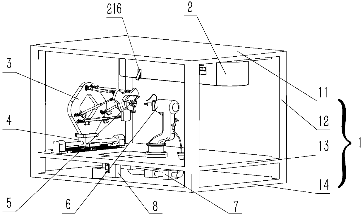
[0049] Such as figure 1 As shown, this embodiment discloses an automatic denture grinding and repairing system, which includes a frame support device 1, an automatic denture transmission device 2, a parallel arm platform device 3, a longitudinal translation device 4, an automatic denture clamping device 5, and a series mechanical Arm device 6, denture collection device 8 and grinding fluid circulation device 7. The frame supporting device 1 comprises an upper top board 11, a middle board 13, a lower base board 14 and a support frame 12, and the upper top board 11, the middle board 13 and the lower base board 14 are all horizontally arranged, and the upper top board 11, the middle board 13 and the lower board 14 are arranged horizontally by the support frame 12. The bottom plate 14 is connected as one; the automatic denture transmission device 2 is set on the upper top plate 11, the longitudinal translation device 4 is set on the middle plate 13, the parallel arm platform devic...
Embodiment 2
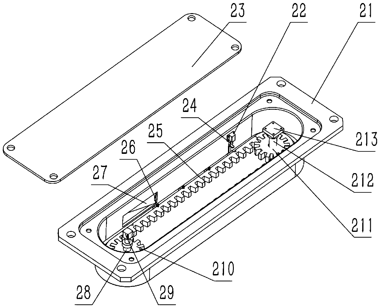
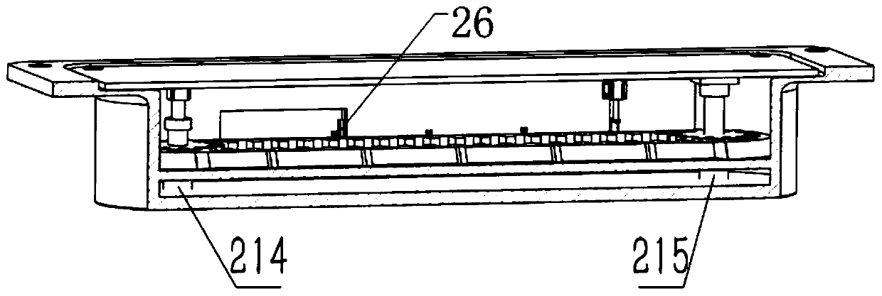
[0051] Such as Figure 2-4 As shown, the present embodiment discloses the structure of the above-mentioned automatic denture transmission device 2 . It includes a long waist shell 21, an upper cover 23, a transmission belt 25, a motor A 29, a pulley A 210, a pulley B 211, a support A 214, a support B 213, a support C 215, and a vertical shaft A 28 , vertical shaft B 212, cylinder A 22, V-shaped chute 216, chute adjuster 217, vertical door panel 24, feeding door panel 27 and door axle 26. The long waist type shell 21 is fixed on the upper top plate 11 of the frame support device 1, the upper cover plate 23 is fixed on the top of the long waist type shell 21, the motor A 29 is fixed on one side of the upper cover plate 23, and the bearing A 214 is The motor A 29 is fixed on one side of the bottom of the inner cavity of the long waist housing 21, and the vertical axis A 28 passes through the pulley A 210 to fix the pulley A 210 between the motor A 29 and the support A 214 Betwe...
Embodiment 3
[0055] This embodiment discloses the structure of the above-mentioned parallel arm platform device 3 . It includes a first flat plate, a second flat plate and three pairs of push rod systems arranged between them. Wherein, each group of push rod systems includes a first universal hinge 33 , a first hinge base 32 , a servo motor 36 , a sleeve 35 , a push rod 34 , a second universal hinge 38 and a second hinge base. The first hinge seat 32 is fixed on the first flat plate, one end of the first universal hinge 33 is connected to the first hinge seat 32, and the other end is connected to one end of the push rod 34, and the other end of the push rod 34 is sleeved in the sleeve 35, and Can slide in the sleeve 35, the bottom end of the sleeve 35 is connected with one end of the second universal hinge 28, and the other end of the second universal hinge 38 is connected with the second hinge seat, and the second hinge seat is fixed on the second plate Above, the servo motor 36 is integ...
PUM
 Abstract
Description
Claims
Application Information
 - R&D
- Intellectual Property
- Life Sciences
- Materials
- Tech Scout
- Unparalleled Data Quality
- Higher Quality Content
- 60% Fewer Hallucinations
Browse by: Latest US Patents, China's latest patents, Technical Efficacy Thesaurus, Application Domain, Technology Topic, Popular Technical Reports.
© 2025 PatSnap. All rights reserved.Legal|Privacy policy|Modern Slavery Act Transparency Statement|Sitemap|About US| Contact US: help@patsnap.com


