
Sputtering target material preparation process based on plasma spraying technology

A preparation process and plasma technology, which are applied in metal material coating process, sputtering coating, ion implantation coating, etc., can solve the problem that the target size is difficult to enlarge, the target particles fall off, the furnace pressure and temperature uniformity are difficult to solve. control issues

Inactive Publication Date: 2019-06-14
芮瑛 +1
View PDF9 Cites 2 Cited by
  • Summary
  • Abstract
  • Description
  • Claims
  • Application Information

AI Technical Summary

Problems solved by technology

High Density Li for Sputtering Targets 3 PO 4 There are two common manufacturing methods for materials, sintering and hot pressing. These two manufacturing methods have some common difficulties: (1) It is difficult to increase the size of the target. There are two key factors here. One is Li 3 PO 4 It is a brittle ceramic material, and mechanical and thermal stress will cause cracking. Second, with the increase of the required furnace size, it becomes more and more difficult to control the furnace pressure and temperature uniformity. This high-purity ceramic material has a relatively small temperature window; (2) joints, as mentioned above, it is difficult to make a large-sized target into one piece, and several pieces need to be connected to make a larger piece. However, Seams can be one of the causes of premature target failure
Welding / bonding is required between the target and the backplane, usually with indium soldering or high-temperature-resistant conductive adhesive, so that the joints are easy to cause pollution; (3) phase purity, high density and pure phase are difficult to exist at the same time, high temperature A common impurity at high pressure is Li 4 P 2 o 7 , which is caused by the loss of LiO2 by lithium phosphate, and different phases may have different sputtering rates, which eventually lead to the falling off of target particles; (4) working gases are usually limited to inert gases and other gases that do not corrode gas chamber components, Otherwise, it will accelerate the loss or damage the components in the reactor, especially the graphite thermal field, so there is no flexibility of the spraying method

Method used


Image

  • Sputtering target material preparation process based on plasma spraying technology
  • Sputtering target material preparation process based on plasma spraying technology
  • Sputtering target material preparation process based on plasma spraying technology

Examples


Embodiment 1

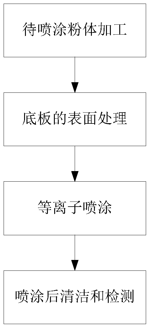
[0033] Such as figure 1 As shown, the sputtering target preparation process based on plasma spraying technology disclosed by the present invention includes the following steps:

[0034] Step 1, processing the powder to be sprayed to a particle size range for plasma spraying;

[0035] Step 2, the surface of the bottom plate is subjected to a surface treatment satisfying plasma spraying;

[0036] Step 3, using a plasma spraying machine to spray the powder to be sprayed prepared in step 1 on the surface of the bottom plate after surface treatment in step 2;


PUM


Abstract

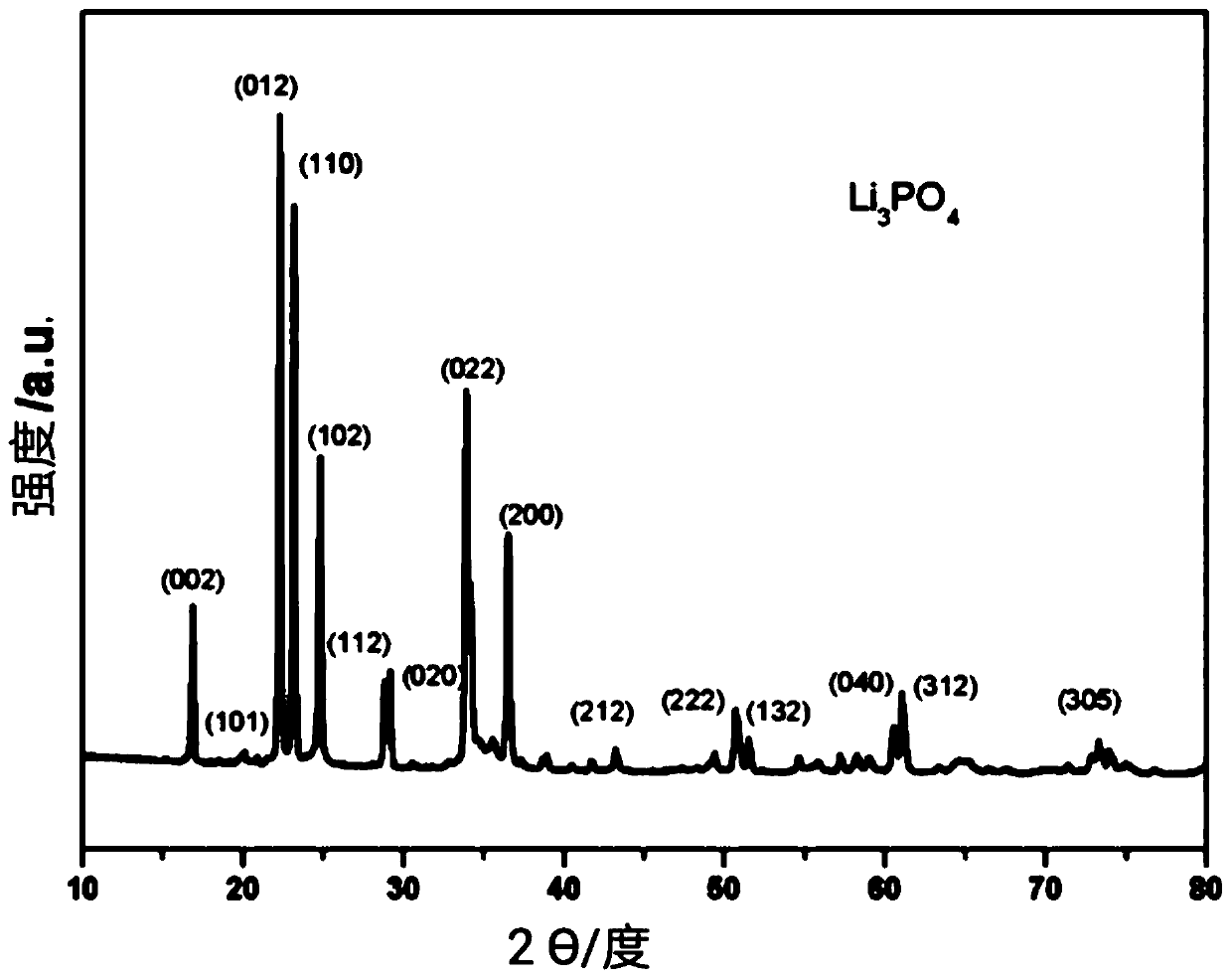
The invention discloses a sputtering target material preparation process based on a plasma spraying technology. The process comprises the steps that to-be-sprayed powder is processed to be within theparticle size range used for plasma spraying; the surface of a bottom board is subjected to surface treatment meeting the plasma spraying; the prepared to-be-sprayed powder is sprayed to the treated surface of the bottom board through a plasma spraying machine; and the sprayed bottom board is cleaned and detected. The sputtering target material preparation process uses the plasma spraying technology for preparing a target material, and the target material gas the high compactness (with the relative density of 93%) and high purity the same as primary powder materials; and compared with a hot pressing or sintering method, the preparation process not only can meet the preparation requirements of large-size target materials meeting the production demands of hull cells, but also can be used formanufacturing of target materials for electrode materials.

Description

technical field [0001] The invention relates to a sputtering target preparation process, in particular to a sputtering target preparation process based on plasma spraying technology. Background technique [0002] Thin-film lithium batteries have several advantages over conventional lithium batteries. The most obvious are small size, high energy density, and long cycle life. A thin-film lithium battery is composed of two electrodes, the cathode and the anode, and an electrolyte. For example, the cathode material can be LiCoO 2 , LiMn 2 o 4 、LiFePO 4 or other materials. The anode can be C, Si, Ge, Sn or various oxides, nitrides or oxynitrides. Lithium phosphorus oxynitride (LiPON) is one of the most commonly used electrolyte materials in thin-film lithium batteries. It is usually produced by physical vapor deposition with lithium phosphate target coating in a nitrogen atmosphere. Existing technologies have shown that the electrolyte is critical to battery performance, ...

Claims


Application Information

Patent Timeline
Patent Type & Authority Applications(China)
IPC IPC(8): C23C14/34C23C4/134C23C4/137C23C4/04
CPCC04B35/447C04B2235/3203C04B2235/81C23C4/02C23C4/18C23C14/3414C23C4/11C23C4/134H01J37/3491H01M4/0426H01M4/24H01M10/0525H01M10/0562H01M2300/0071Y02E60/10C23C14/0605C23C14/0652C23C14/083C23C14/085C23C14/14H01M4/505
Inventor 芮瑛吉和林
Owner 芮瑛
Learn More