Mixer

A technology of mixer and mixing section, which is applied in the direction of machines/engines, noise reduction devices, engine components, etc., and can solve problems such as unfavorable mixing of exhaust gas and urea solution, large exhaust resistance, and poor noise reduction ability

Pending Publication Date: 2019-06-04
WEICHAI POWER CO LTD
View PDF0 Cites 5 Cited by
  • Summary
  • Abstract
  • Description
  • Claims
  • Application Information

AI Technical Summary

Problems solved by technology

[0003] As far as the existing technology is concerned, in order to reduce the power loss ratio and exhaust back pressure of diesel engines, the acoustic performance is often sacrificed, resulting in insertion loss that cannot meet the design requirements; insertion loss is the sound power level at the outlet of the system before and after the insertion of the muffler element difference
[0004] At present, the aftertreatment mixer of national VI diesel engine generally adopts the swirl tube structure, which is not conducive to the mixing of exhaust gas and urea solution in the case of large air flow, and has high local air velocity, poor noise reduction ability, and large exhaust resistance The problem

Method used


Image

  • Mixer
  • Mixer
  • Mixer

Examples


Embodiment Construction

[0031] The core of this specific embodiment is to provide a mixer, which can optimize the post-processing mixer and achieve good acoustic performance, which solves the current problems in this field.

[0032] Hereinafter, an embodiment will be described with reference to the drawings. In addition, the examples shown below do not limit the content of the invention described in the claims in any way. In addition, all the contents of the configurations shown in the following embodiments are not limited to be essential to the solution of the invention described in the claims.

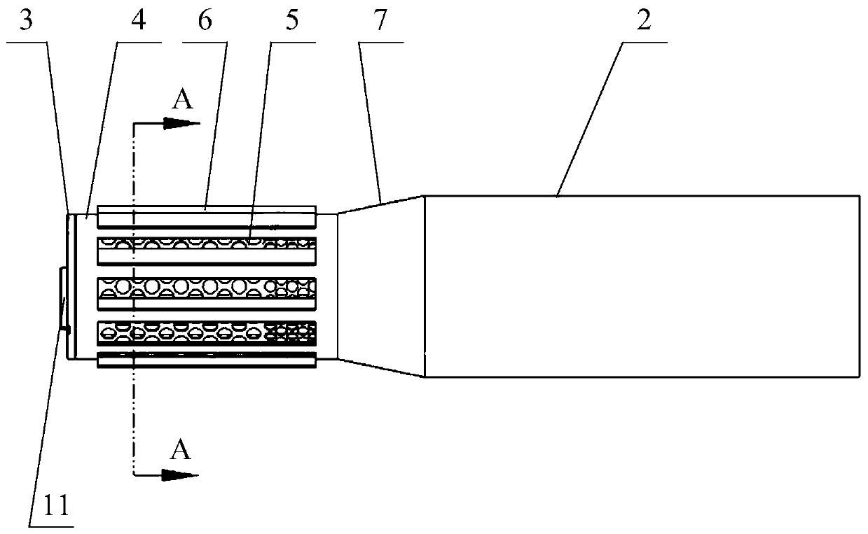
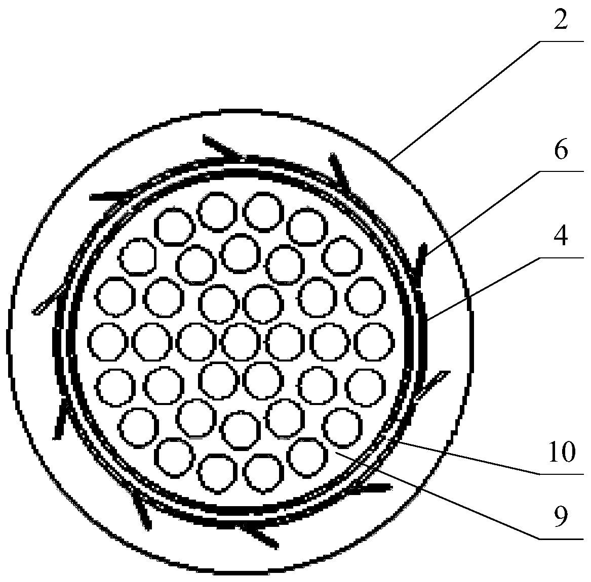
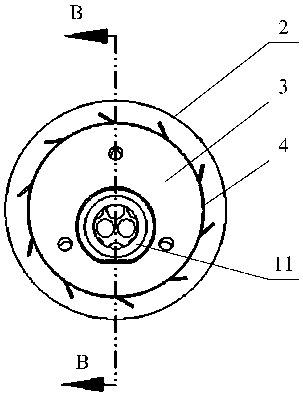
[0033] For the mixer provided in this specific embodiment, please refer to Figure 1-5 ; Including mixing section 1 and expansion section 2; wherein, one end of mixing section 1 is provided with urea nozzle base 3 for mixing exhaust gas and urea entering the mixer; the pipe diameter of expansion section 2 is larger than the pipe diameter of mixing section 1, expanding One end of the section 2 is provided ...


PUM


Abstract

The invention discloses a mixer. The mixer comprises a mixing section and an expanding section, wherein one end of the mixing section is provided with a urea nozzle base, and the mixing section is used for mixing waste gas with urea in the mixer; and the pipe diameter of the expanding section is larger than that of the mixing section, one end of the expanding section is provided with a port matched with the pipe diameter of the mixing section, and the other end of the mixing section is connected with the port. According to the mixer, the mixing section and the expanding section of the mixer are directly connected, and thus, after mixing is completed, the waste gas and the urea directly enter the expanding section; and the pipe diameter of the expanding section is larger than that of the mixing section, thus, when the mixed gas enters the expanding section, the pipe diameter is suddenly changed, the circulation resistance is reduced, acoustic impedance change is caused, accordingly, part of sound waves spreading along a pipeline is reflected back to a sound source, and the gas flow generates the capacity for reducing the sound at the specific frequency band. Thus, through the mixedprovided by the invention, an aftertreatment mixer can be optimized, the good acoustic performance is achieved, and the problems in the field at the present stage are solved.

Description

technical field [0001] The invention relates to the field of aftertreatment of exhaust gas, more specifically, to a mixer. Background technique [0002] With the increasingly stringent emission regulations, the aftertreatment technology of diesel engines has gradually changed from a single urea selective catalytic reduction agent SCR to a combination of catalytic oxidizer DOC + particulate filter DPF + selective catalytic reduction agent SCR, and the emission in China VI and higher are becoming more and more widely used. [0003] As far as the existing technology is concerned, in order to reduce the power loss ratio and exhaust back pressure of diesel engines, the acoustic performance is often sacrificed, resulting in insertion loss that cannot meet the design requirements; insertion loss is the sound power level at the outlet of the system before and after the insertion of the muffler element difference. [0004] At present, the aftertreatment mixer of national VI diesel ...

Claims


Application Information

Patent Timeline
IPC IPC(8): F01N3/28F01N3/20F01N1/06
Inventor 张中业王子敬徐止听
Owner WEICHAI POWER CO LTD
Why Eureka
Try Eureka