


Quick Research
Generate reliable direction feasibility study reports for your R&D in just a few steps.

Technical Q&A
Discover and master advanced knowledge NOW. Basics, ideas, possibilities, all at once.

Find Solutions
As an expert in R&D theories, this can generate solutions to your technical problems instantly.

Evaluate Feasibility
Analyze your overall solution with one click, know your potential R&D risks in advance.

Monitor Landscape
Get weekly tech updates, stay abreast of the latest tech innovations and key insights.
A magnetic circuit structure of a sputtering ion pump and the sputtering ion pump
An ion pump and magnetic circuit technology, applied in the direction of ion diffusion discharge tube, particle separation tube, etc., can solve the problems of difficult to achieve ideal magnetic field conditions, lack of magnetic circuit optimization, and insufficient use of magnetic field, and achieve dense and uniform distribution of magnetic lines of force. , The effect of reducing the processing difficulty and the requirement of magnet size
- Summary
- Abstract
- Description
- Claims
- Application Information
AI Technical Summary
Problems solved by technology
Method used
Image

Examples
Embodiment 1
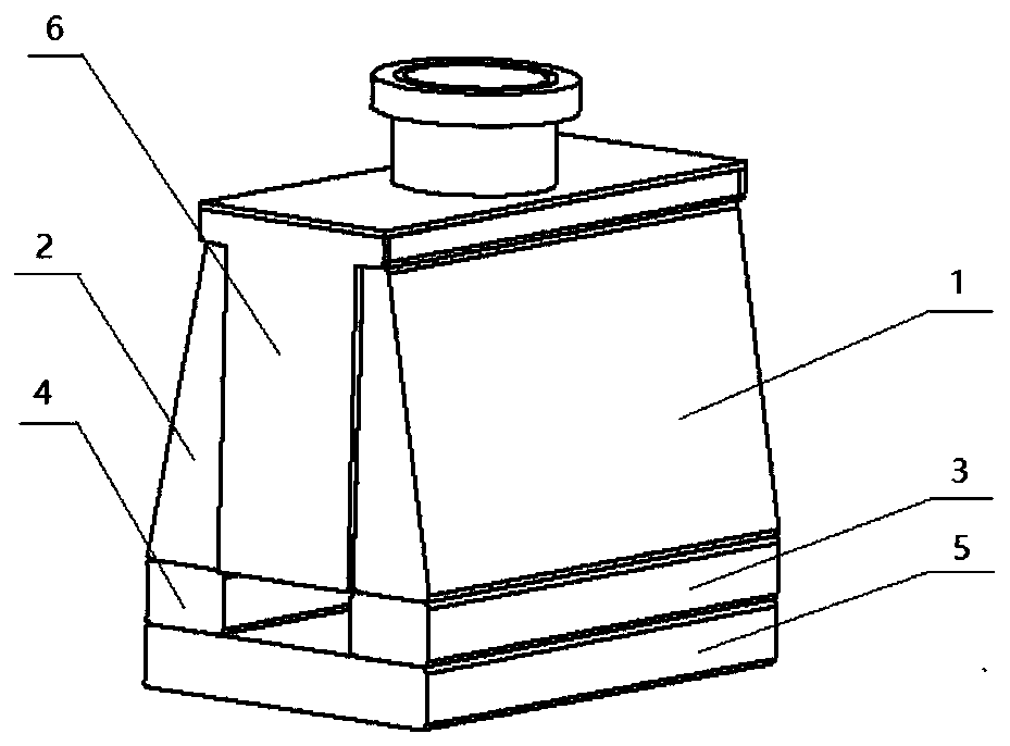
[0080] An improved sputtering ion pump magnetic circuit structure is used to provide the necessary magnetic field environment for the pumping components, such as figure 1 As shown, it includes an air extraction assembly 6, a pair of stepped yokes (stepped yoke A 1 and stepped yoke B 2), a pair of magnets (magnet A3 and magnet B 4) and a lower yoke 5. Among them, a pair of stepped yokes and a pair of magnets distributed below them, and a yoke is placed under the magnets, and the magnets and the yokes are connected by screws. The bottom of the stepped yoke is wide and the top is narrow, and the vertical surfaces of a pair of stepped yokes are oppositely arranged, and an air extraction assembly is arranged between them. The upper right-angled trapezoidal table-shaped magnetic yoke conducts the magnetic force lines to the surface facing the entire air extraction assembly, then passes through the air extraction assembly evenly to the right yoke, and then recovers all the magnetic f...
Embodiment 2
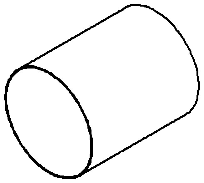
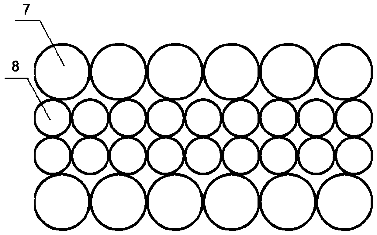
[0084] This embodiment is based on Embodiment 1, and further designs the magnetic circuit structure of the sputtering ion pump, wherein the structure of the anode cylinder is as follows figure 2 As shown, the diameter of the large-diameter anode cylinder 7 is 24mm, the diameter of the small-diameter anode cylinder 8 is 16mm, and the length is 25mm. The two anode cylinders are formed into an anode cylinder group by spot welding, and the large-diameter anode copper is set Above and below, the small-diameter anode cylinder is set in the middle, and the structure is as image 3 shown. The insulating block is divided into insulating block A 9 and insulating block B 10, and its structure is as follows Figure 4 As shown, the wall thickness is 2mm, and the inner wall of the insulating block A and the insulating block A are provided with four brackets with a rounded corner diameter of 24mm, which are distributed at the four corners of the insulating block to support the anode cylind...
Embodiment 3
[0087] A magnet and a yoke are placed outside the air extraction assembly to provide it with a magnetic field. The difference in the placement of the magnet and the yoke will cause changes in the magnetic circuit around the air extraction assembly, thereby changing the magnetic field distribution in the air extraction assembly. In this embodiment, software simulation is used to determine the field distribution type. Four arrangement types of magnets and yokes will be selected to simulate the magnetic field. The specific structure is as follows: Figure 10shown. The number 6 in the figure is the air extraction assembly, the number 18 is the magnet material, and the number 19 is the yoke material. Figure (a) shows the ordinary magnetic field distribution. Only two magnets are placed on both sides of the air extraction component. The magnetic field has no constraints. This type mainly serves as a comparison with other types of magnetic field distribution. Figure (b) shows the m...
PUM
| Property | Measurement | Unit |
|---|---|---|
| diameter | aaaaa | aaaaa |
| diameter | aaaaa | aaaaa |
| length | aaaaa | aaaaa |
Abstract
Description
Claims
Application Information
 - R&D Engineer
- R&D Manager
- IP Professional
- Industry Leading Data Capabilities
- Powerful AI technology
- Patent DNA Extraction
Browse by: Latest US Patents, China's latest patents, Technical Efficacy Thesaurus, Application Domain, Technology Topic, Popular Technical Reports.
© 2024 PatSnap. All rights reserved.Legal|Privacy policy|Modern Slavery Act Transparency Statement|Sitemap|About US| Contact US: help@patsnap.com