
Equipment suitable for high-temperature molten material cooling and waste heat recycling

A technology of high-temperature melting and waste heat recovery, applied in lighting and heating equipment, treatment of discharged materials, waste heat treatment, etc. Problems such as low waste heat recovery rate can solve the serious waste of water resources, improve the working environment and reduce energy consumption

Pending Publication Date: 2019-05-31
史晓云 +1
View PDF4 Cites 4 Cited by
  • Summary
  • Abstract
  • Description
  • Claims
  • Application Information

AI Technical Summary

Problems solved by technology

[0005] (1) High water consumption: This is a particularly serious problem for countries with severe water shortages
[0006] (2) A large amount of H is produced in the process of water quenching slag 2 S and SOx enter the atmosphere with steam, causing environmental pollution
[0007] (3) There is no recovery of sensible heat of slag: liquid blast furnace slag at 1450-1500 °C has great waste heat utilization value, but the recovery rate of waste heat of blast furnace slag in China is very low, only about 10%
[0008] (4) Drying treatment is required: the water content of blast furnace slag is as high as 10%, and it must be dried when used as cement raw material, which still consumes a certain amount of energy
When the system works, the rollers rotate in opposite directions, and the high-temperature molten slag is extruded on the rollers for a very short cooling distance. In the vertical position, the slag may not condense into a solid state, but falls into the cold slag tank under the action of gravity; from the vertical position to Furnace material at the slag cleaning board may fall off randomly. These factors will lead to large differences in the particle size of solid slag in the cold slag tank, which will affect the uniformity of cooling air passing through the cold slag tank.

Method used


Image

  • Equipment suitable for high-temperature molten material cooling and waste heat recycling
  • Equipment suitable for high-temperature molten material cooling and waste heat recycling
  • Equipment suitable for high-temperature molten material cooling and waste heat recycling

Examples


Embodiment Construction

[0049] The present invention will be described in further detail below in conjunction with specific examples, but not as a limitation of the present invention.

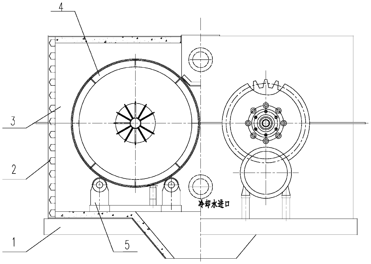
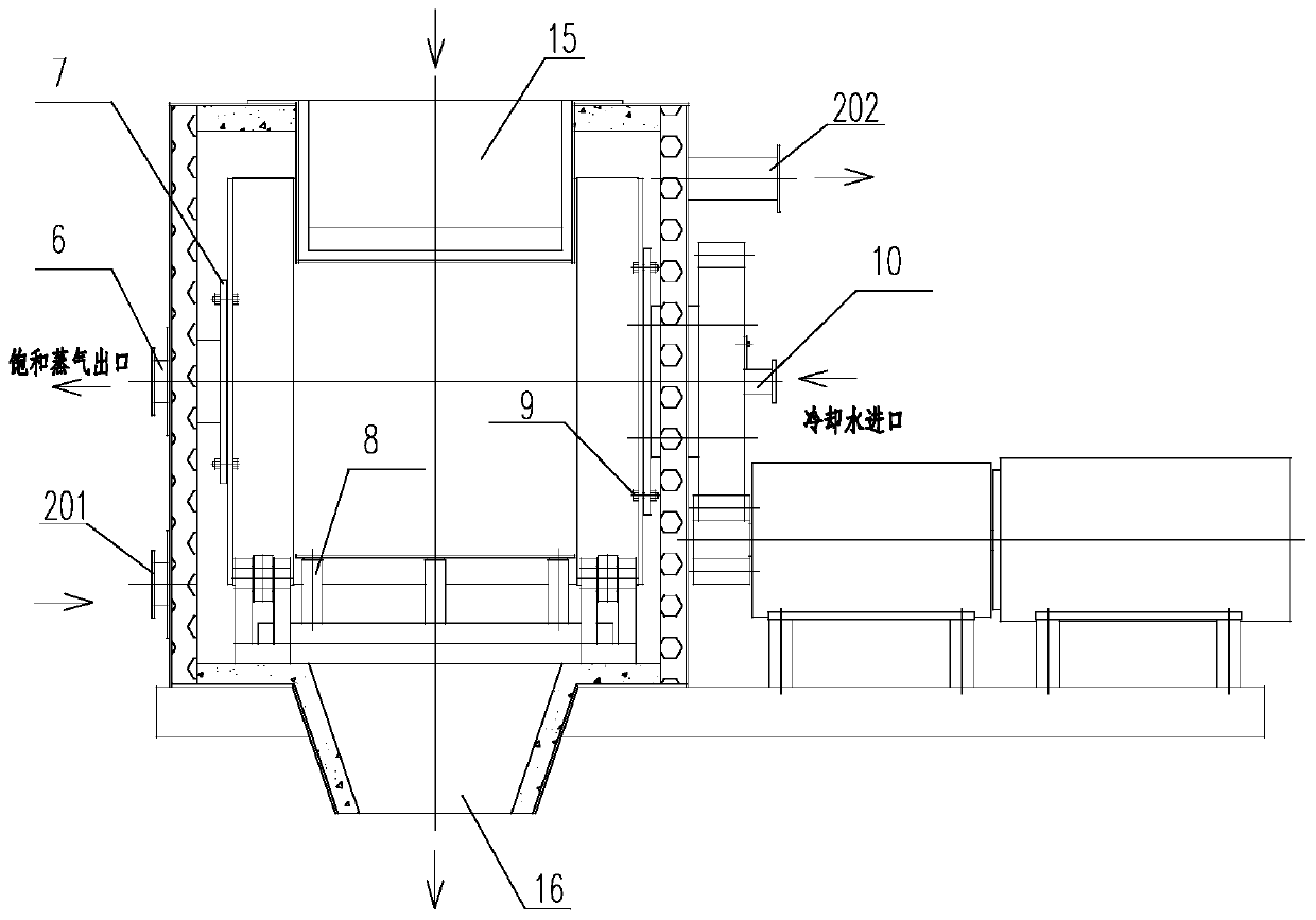
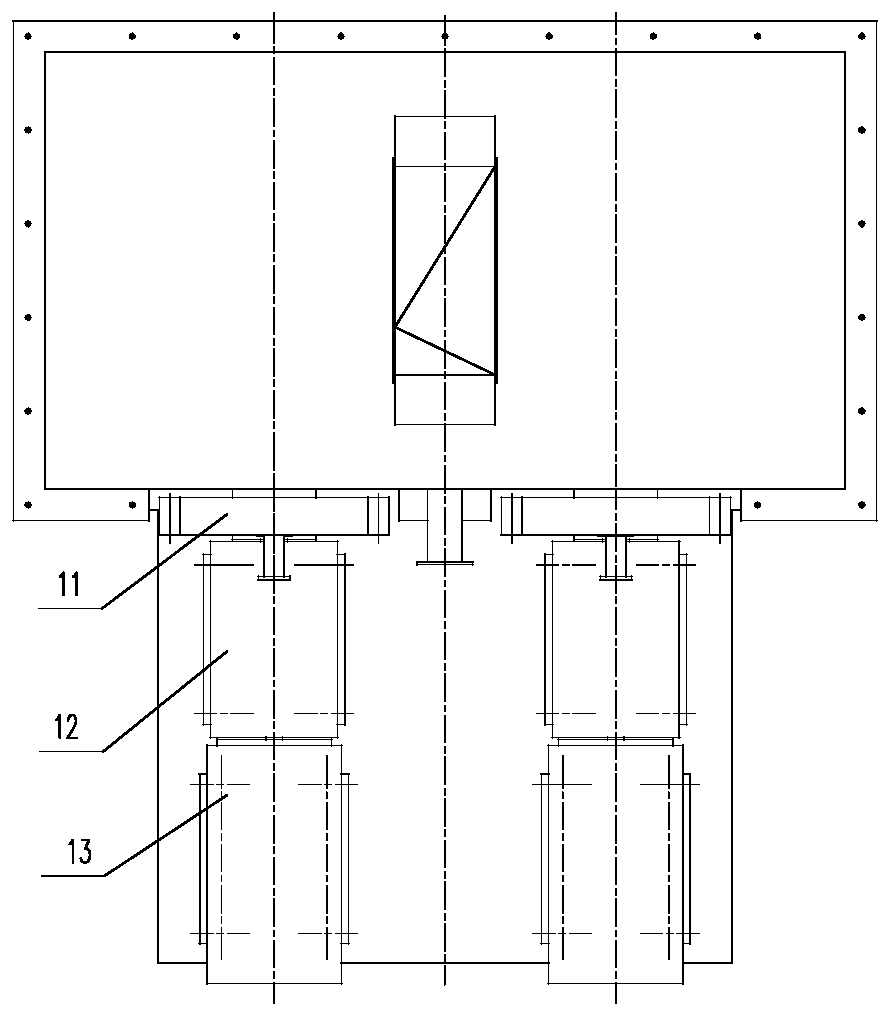
[0050] Such as Figure 1-3 As shown, the present invention is suitable for high-temperature molten material cooling and waste heat recovery equipment, and consists of a roller cooler body, a reducer 12, a gear transmission 11, a motor 13, a base 1, an on-site monitoring instrument, and material import and export pipelines, etc. The body of the roller cooling machine includes a shell 3, a pair of rollers 4, a support device 5, an exhaust device 6, a scraper 8 and a feed water cooling device 10.

[0051] The shell 3 is installed on the base 1, and the roller pair 4 is composed of two counter-rotating rollers 401. The rollers 401 are installed in the shell 3 through the support device 5, and the motor 13, deceleration and The device 12 and the gear transmission device 11 are driven to rotate, and the inside of the rolle...


PUM


Abstract

The invention discloses equipment suitable for high-temperature molten material cooling and waste heat recycling. A molten material is fed into the middle of a roller pair from a feed inlet and is carried over along with the rotation of the two rollers so as to form a liquid film; cooling water enters a shell water-cooled wall through a water supply pipeline and absorbs sensible heat of the high-temperature molten material so as to enter the rollers through a pipeline and be sprayed to the inner wall surfaces of the cooling rollers through a nozzle group of a cooling spraying system; the cooling water absorbs heat of the inner walls of the rollers so as to be phase-changed into steam; solidification heat of the high-temperature molten material is absorbed; the steam is discharged through asteam discharge device; the sensible heat and the solidification heat of the high-temperature molten material during the cooling process are recycled through the water-cooled wall and the cooling water fed into the rollers, so that the waste heat recycling utilization ratio is high; and the high-temperature material can be quickly cooled through heat absorption for two times, so that the heat exchange efficiency is high, and the working efficiency is high.

Description

technical field [0001] The invention relates to the field of energy recovery, in particular to a device suitable for cooling high-temperature molten materials and recovering waste heat. Background technique [0002] Waste heat is the energy that is not used in energy utilization equipment under certain economic and technical conditions, that is, redundant and waste energy. It includes seven kinds of high-temperature exhaust gas waste heat, cooling medium waste heat, waste steam and wastewater waste heat, high-temperature product and slag waste heat, chemical reaction waste heat, combustible waste gas waste liquid and waste heat, and high-pressure fluid waste pressure. According to the survey, the total waste heat resources of various industries account for about 17%-67% of their total fuel consumption, and the recyclable waste heat resources are about 60% of the total waste heat resources. Among them, high-temperature products and slag waste heat mainly come from a large am...

Claims


Application Information

Patent Timeline
IPC IPC(8): F27D15/02F27D17/00
CPCY02P10/25
Inventor 史晓云支小强
Owner 史晓云
Learn More