
Method for improving strength of insulator at discharging end of ignition electric nozzle of aviation engine

An aero-engine and insulator technology, which is used in the field of aviation and aerospace engine ignition, can solve the problems of insulator cracks at the discharge end and reduce the stress on the discharge end of the insulator, and achieve the effects of reduced stress, high efficiency and concentrated ignition.

Active Publication Date: 2019-04-16
SHAANXI AVIATION ELECTRICAL
View PDF9 Cites 3 Cited by
  • Summary
  • Abstract
  • Description
  • Claims
  • Application Information

AI Technical Summary

Problems solved by technology

[0004] In order to solve the problem that the insulator at the discharge end of the existing ignition nozzle is prone to cracks, the present invention proposes a method for improving the strength of the insulator at the discharge end of the ignition nozzle of an aeroengine, retaining the characteristics of concentrated ignition and high efficiency of the recessed structure, and at the same time reducing the discharge end of the insulator. The stress on the parts meets the requirements of adapting to the engine environment and provides the engine with a high-reliability main ignition nozzle

Method used


Image

  • Method for improving strength of insulator at discharging end of ignition electric nozzle of aviation engine
  • Method for improving strength of insulator at discharging end of ignition electric nozzle of aviation engine
  • Method for improving strength of insulator at discharging end of ignition electric nozzle of aviation engine

Examples


Embodiment Construction

[0021] Embodiments of the present invention are described in detail below, and the embodiments are exemplary and intended to explain the present invention, but should not be construed as limiting the present invention.

[0022] In this embodiment, the insulator material and the use environment scene are analyzed, the force of the insulator is theoretically calculated, the improvement plan is determined, and the simulation verification is carried out.

[0023] 1. Insulator material analysis

[0024] The insulator material is GLC-58 alumina ceramics, with Al 2 o 3 as the main body, Al 2 o 3 The content is more than 95%, adding other metal oxide components as additives, mixing evenly according to a certain proportion, and then processing through calcination, ball milling, sieving, plasticizing, molding, aging, bisque firing, roasting, and performance testing. The sintering temperature is 1650-1700°C.

[0025] Ceramic materials are brittle materials, the fracture of brittle m...


PUM


Abstract

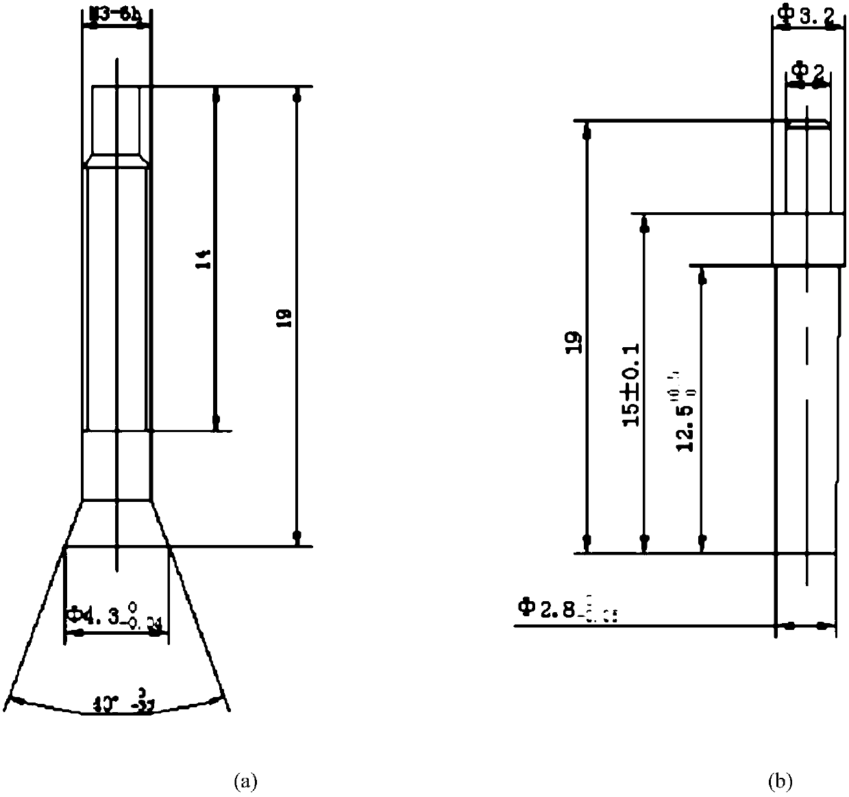
The invention proposes a method for improving strength of an insulator at a discharging end of an ignition electric nozzle of aviation engine. The total length of the insulator and a central electrodeis maintained unchanged, the size of an insulator part and the size of a central electrode part are changed, and conical-surface matching between the central electrode and the insulator is changed tostraight-surface matching; with regard to the insulator, the discharging end of the insulator is changed to a straight surface to a conical surface, the wall thickness of an end part is increased by0.5 millimeter, the size of an inner hole of the discharging end is Phi 2.8 millimeters, the chamfer angle of the end part is 60 degrees, and the axial length of the chamfer angle at the end part is 0.5 millimeter; a straight table is additionally arranged at an outer circle of the insulator, and the situation that a bottom surface of the shell cannot be completely cleared to cause point contact is prevented; and with regard to the central electrode, the conical surface of the discharging end of the central electrode is changed to the straight surface, and the diameter of the discharging end of the central electrode is Phi 2.8 millimeters. The characteristics of ignition concentration and high efficiency of a sunken structure are maintained, meanwhile, the stress of a discharging end partof the insulator is reduced, the application requirement applicable to the engine environment is met, and a reliable main ignition electric nozzle is provided for the engine.

Description

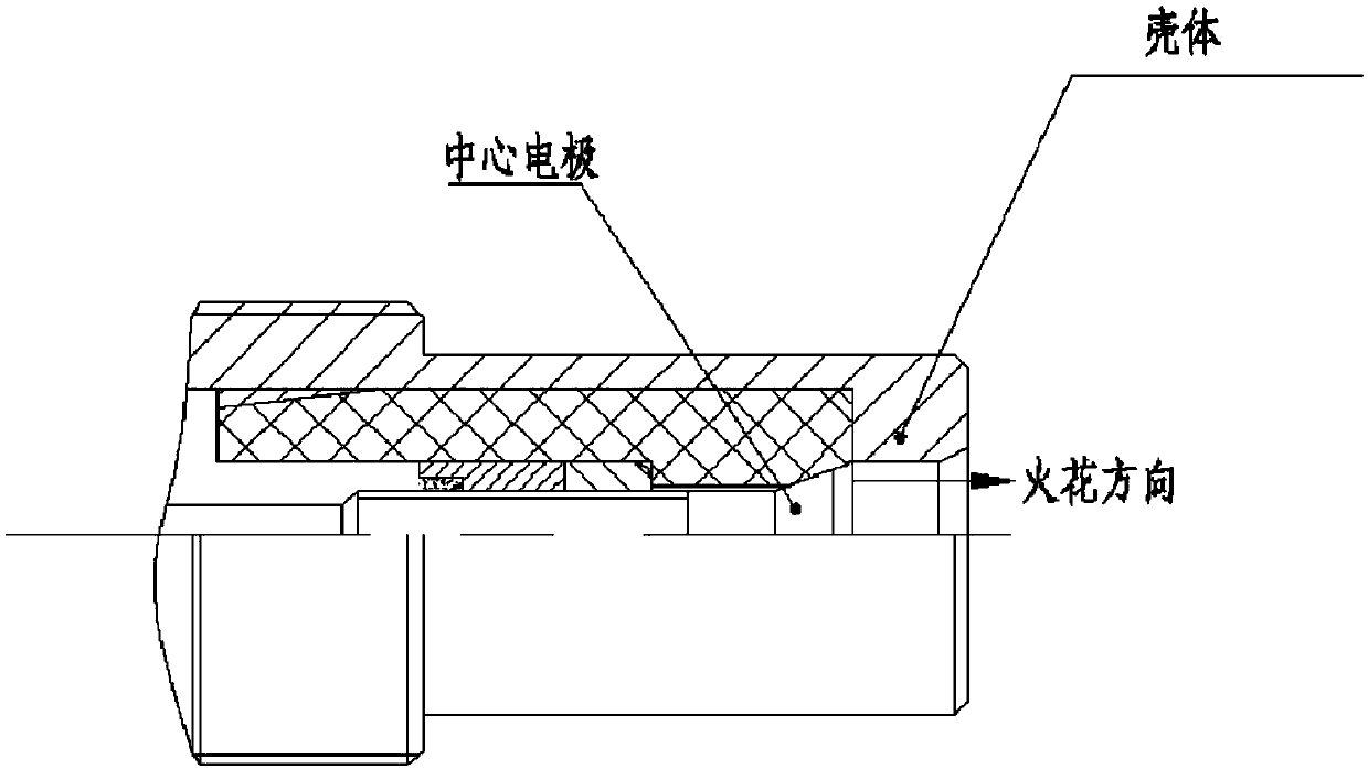
technical field [0001] The invention belongs to the field of aviation and aerospace engine ignition, in particular to a method for improving the strength of an insulator at a discharge end of an ignition nozzle of an aeroengine. Background technique [0002] At present, during the engine test run of an aero-engine ignition nozzle, there have been many failures of cracks in the insulator at the discharge end, which cannot meet the high-temperature, vibration and other environmental requirements of the engine. [0003] The ignition nozzle adopts a concave structure - the center electrode and the tapered insulator form ( figure 1 ). In the process of cooling back with the high temperature of the engine, since the axial shrinkage of the metal center electrode is greater than the axial shrinkage of the ceramic insulator, the outer cone of the center electrode will generate axial pressure on the inner cone of the insulator. When the concentrated stress exceeds the insulator mater...

Claims


Application Information

Patent Timeline
IPC IPC(8): H01T13/20F02C7/266
CPCF02C7/266H01T13/20
Inventor 李星星章雅玲朱琛陈钢锋
Owner SHAANXI AVIATION ELECTRICAL
Learn More