Liquid crystal display device and driving method
A technology of a liquid crystal display device and a driving method, which is applied to static indicators, instruments, nonlinear optics, etc., can solve the problems of gray scale inversion at large viewing angles, application of large voltages, and contrast reduction, so as to increase contrast and achieve mutual Compensate and improve the effect of display quality
- Summary
- Abstract
- Description
- Claims
- Application Information
AI Technical Summary
Problems solved by technology
Method used
Image

Examples
Embodiment 1
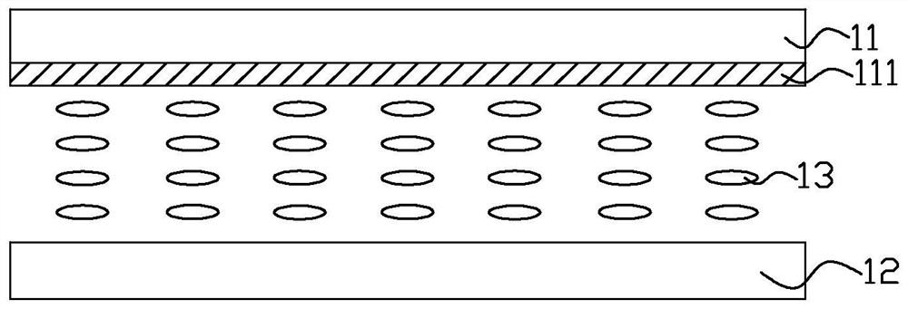
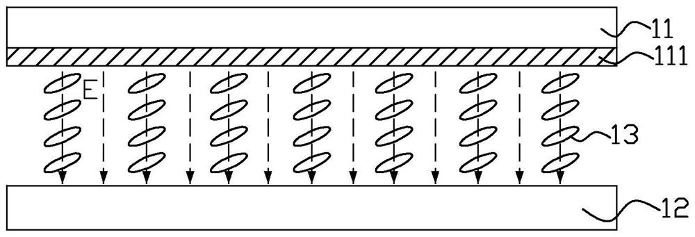
[0036] Such as image 3 , Figure 5 and Figure 6 As shown, a liquid crystal display device provided by Embodiment 1 of the present invention includes: a first substrate 20 , a second substrate 30 opposite to the first substrate 20 , and a liquid crystal between the first substrate 20 and the second substrate 30 Layer 40. The first substrate 20 is a color filter substrate, and the second substrate 30 is a thin film transistor array substrate. The liquid crystal layer 40 uses positive liquid crystal molecules, that is, liquid crystal molecules with positive dielectric anisotropy. Figure 5 It is a schematic diagram of the cross-sectional structure of the liquid crystal display device at M-M in FIG. 3 at a wide viewing angle in this embodiment. At this time, the liquid crystal is parallel to the two substrates. Figure 6 For liquid crystal display devices at narrow viewing angles image 3 The schematic diagram of the cross-sectional structure at M-M in the middle, at this t...
Embodiment 2
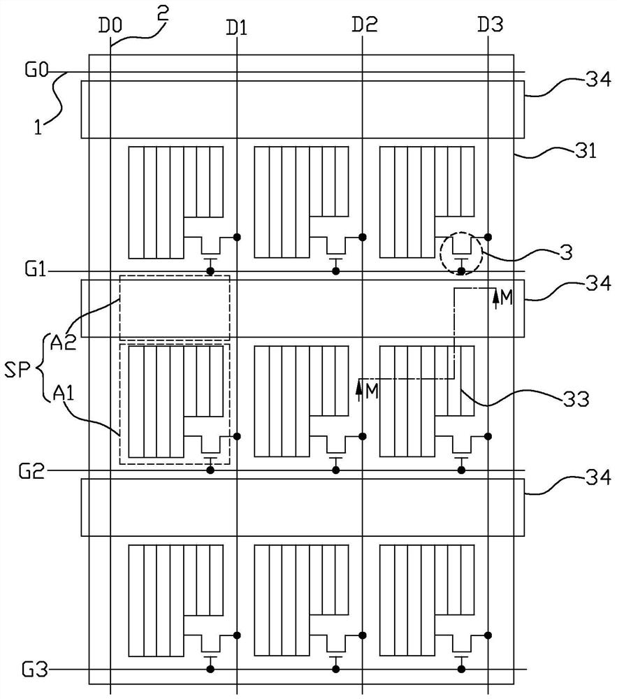
[0054] Such as Figure 4 As shown, a liquid crystal display device and a driving method provided in Embodiment 2 of the present invention are the same as Embodiment 1 ( image 3 ) in the liquid crystal display device and the driving method are basically the same, the difference is that in this embodiment, each auxiliary electrode strip 34 corresponds to the second area A2 covering all sub-pixels SP in each column, and the plurality of auxiliary electrode strips 34 Extending along the direction of the data line 2 , each pixel electrode 33 of the comb structure is perpendicular to the direction of the auxiliary electrode strip 34 . An auxiliary electrode strip 34 is provided between every two adjacent data lines 2, and in each sub-pixel SP, the first area A1 is located on the right side of the second area A2, and the thin film transistor 3 is correspondingly located in the second area the right side of A2, and connect the pixel electrode 33 to the corresponding scan line 1 and ...
Embodiment 3
[0057] Such as Figure 7 , Figure 9 and Figure 10 As shown, a liquid crystal display device and a driving method provided by Embodiment 3 of the present invention are the same as Embodiment 1 ( image 3 ) in the liquid crystal display device and driving method are basically the same, the difference is that, in this embodiment, the common electrode 31 includes a plurality of common electrode strips 31a that are conductively connected (for example, can be conductively connected in the non-display area), and a plurality of Auxiliary electrode strips 34 and a plurality of common electrode strips 31a extend along the scanning line 1 direction, an auxiliary electrode strip 34 and a common electrode strip 31a are arranged between every two adjacent scanning lines 1, and the plurality of auxiliary electrode strips 34 and A plurality of common electrode strips 31a are located on the same layer and arranged alternately, wherein each common electrode strip 31a corresponds to the seco...
PUM
 Abstract
Description
Claims
Application Information
 - Generate Ideas
- Intellectual Property
- Life Sciences
- Materials
- Tech Scout
- Unparalleled Data Quality
- Higher Quality Content
- 60% Fewer Hallucinations
Browse by: Latest US Patents, China's latest patents, Technical Efficacy Thesaurus, Application Domain, Technology Topic, Popular Technical Reports.
© 2025 PatSnap. All rights reserved.Legal|Privacy policy|Modern Slavery Act Transparency Statement|Sitemap|About US| Contact US: help@patsnap.com