
Flat heat pipe with gradient wetting structure

A flat plate heat pipe and gradient wetting technology, which is applied in heat transfer modification, heat exchange equipment, indirect heat exchangers, etc., can solve the problems of increasing heat transfer resistance of heat pipes, difficulty in guaranteeing sintering quality, and large thermal resistance of liquid-absorbing cores, etc. problem, to achieve the effect of reducing heat transfer resistance, reducing heat transfer resistance, and enhancing heat transfer efficiency

Inactive Publication Date: 2019-03-29
XI AN JIAOTONG UNIV
View PDF7 Cites 10 Cited by
  • Summary
  • Abstract
  • Description
  • Claims
  • Application Information

AI Technical Summary

Problems solved by technology

[0004] However, the existing flat heat pipe mainly relies on the capillary force provided by the liquid-absorbing core to push the working fluid backflow, and because the evaporation surface and the condensation surface are covered with liquid-absorbing cores, the thermal resistance of the porous-structured liquid-absorbing core is relatively large, which increases the thermal resistance of the entire heat pipe. Thermal resistance
In addition, the sintered liquid-absorbent core structure itself needs energy consumption, and the sintered quality is difficult to guarantee

Method used


Image

  • Flat heat pipe with gradient wetting structure
  • Flat heat pipe with gradient wetting structure
  • Flat heat pipe with gradient wetting structure

Examples


Embodiment Construction

[0032] In order to enable those skilled in the art to better understand the solutions of the present invention, the following will clearly and completely describe the technical solutions in the embodiments of the present invention in conjunction with the drawings in the embodiments of the present invention. Obviously, the described embodiments are only It is an embodiment of a part of the present invention, but not all embodiments. Based on the embodiments of the present invention, all other embodiments obtained by persons of ordinary skill in the art without making creative efforts shall fall within the protection scope of the present invention.

[0033] It should be noted that the terms "first" and "second" in the description and claims of the present invention and the above drawings are used to distinguish similar objects, but not necessarily used to describe a specific sequence or sequence. It is to be understood that the data so used are interchangeable under appropriate ...


PUM


Abstract

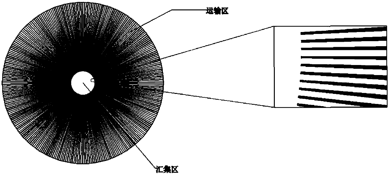
The invention discloses a flat heat pipe with a gradient wetting structure. The flat heat pipe comprises a bottom plate, a top plate and supporting plates located between the bottom plate and the topplate. The bottom plate, the top plate and the supporting plates on both sides are connected to form a sealed cavity. A micron-grade radial strip is machined on the inner surface of the bottom plate,and the wetting gradient which is evenly changed from the circle center to the circumference is presented. Super-hydrophilic super-hydrophobic radial structures arranged at intervals are machined on the inner surface of the top plate and used for transporting condensate to the surrounding pipe wall direction. Liquid absorbing cores are arranged on the inner sides of the supporting plates. Since micro-nano machining is carried out on the evaporation surface, the functions of transporting liquid directionally without pump and concentrating the reflux condensate are achieved. Patterning super-hydrophilic super-hydrophobic machining is carried out on the condensation surface, condensate is driven to migrate to the surrounding pipe wall direction, the condensate backflow speed is increased, liquid absorption core structures on the upper and lower surfaces are omitted, heat resistance is reduced, the evaporation and condensation speed is improved, heat exchange performance of an evaporationarea and a condensation area is improved, and therefore the heat exchange performance of a whole flat heat pipe is improved.

Description

technical field [0001] The invention belongs to the technical field of cooling devices for electronic components, and relates to a flat heat pipe with a gradient wetting structure. Background technique [0002] With the rapid development of electronic technology, electronic components are gradually developing toward miniaturization, high speed and high frequency, and high integration. The functions are becoming more and more complex, and the heat flux density of heat dissipation is getting higher and higher, resulting in an increase in the failure rate of electronic equipment. Therefore, realizing efficient heat dissipation of electronic components and ensuring the reliability of electronic components is a current technical difficulty and research hotspot. [0003] The flat plate heat pipe is a high-efficiency phase change heat transfer equipment improved on the basis of the traditional heat pipe. It has the advantages of simple structure, good temperature uniformity and hig...

Claims


Application Information

Patent Timeline
IPC IPC(8): F28D15/04
CPCF28D15/043F28D15/0233F28D15/046F28F2245/02F28F2245/04F28F2255/18F28F13/003F28F2255/00F28F2260/02F28F2275/06
Inventor 齐宝金魏进家王雅于婷崔晨乙
Owner XI AN JIAOTONG UNIV
Learn More