


Quick Research
Generate reliable direction feasibility study reports for your R&D in just a few steps.

Technical Q&A
Discover and master advanced knowledge NOW. Basics, ideas, possibilities, all at once.

Find Solutions
As an expert in R&D theories, this can generate solutions to your technical problems instantly.

Evaluate Feasibility
Analyze your overall solution with one click, know your potential R&D risks in advance.

Monitor Landscape
Get weekly tech updates, stay abreast of the latest tech innovations and key insights.
Descaling device for machining building steel plates
A technology for construction steel plates and steel plates, which is applied in the field of derusting devices for construction steel plate processing, which can solve problems such as insufficient contact between the derusting agent and the outer surface of the steel plate, difficulty in meeting the needs of derusting processing, and sufficient contact with deep rust to achieve high efficiency. Rust removal effect, improvement of rust removal efficiency, and low production cost
- Summary
- Abstract
- Description
- Claims
- Application Information
AI Technical Summary
Problems solved by technology
Method used
Image


Examples
Embodiment 1
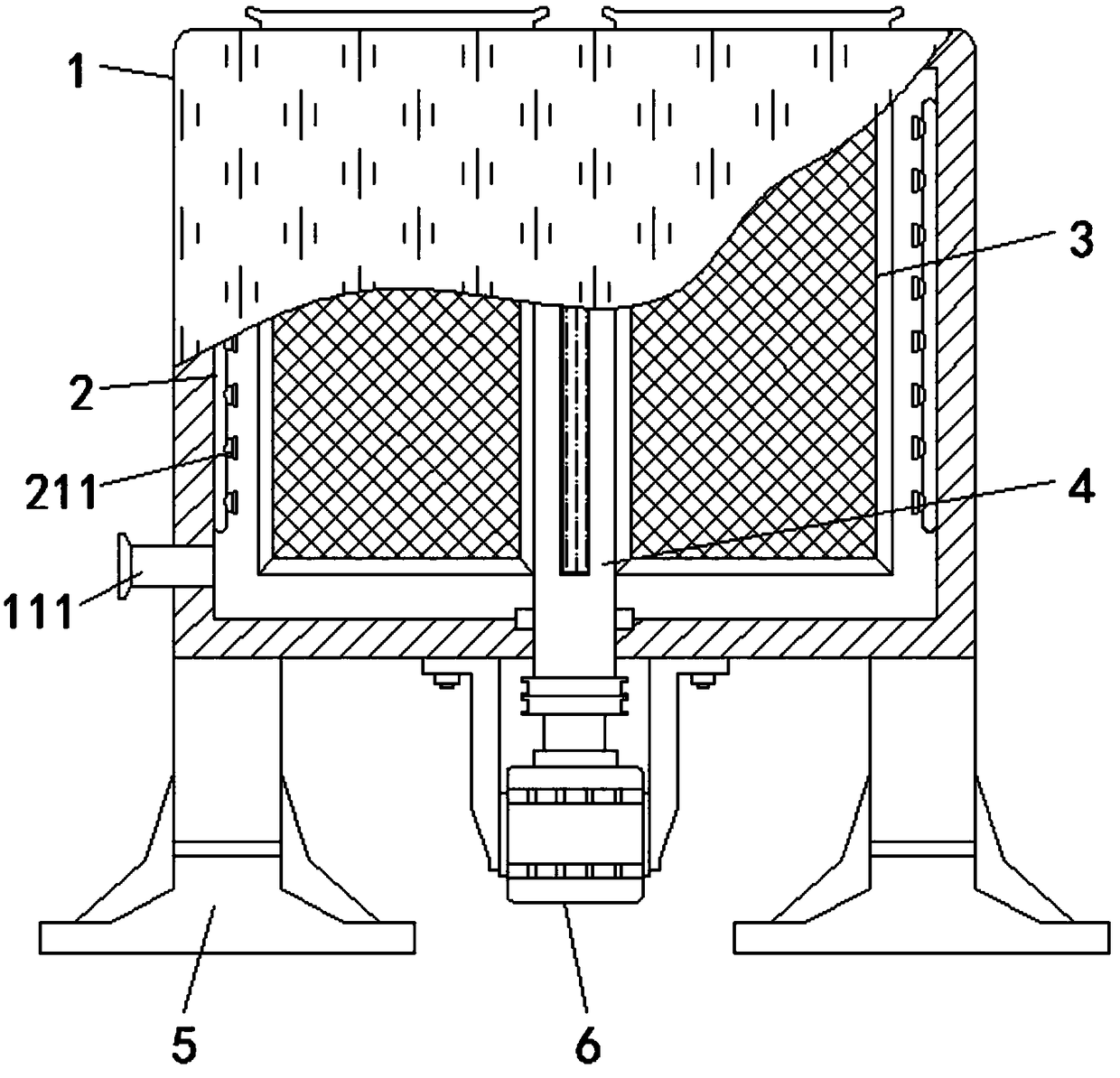
[0030] Embodiment one, with reference to figure 1 and Figure 4 , a rust removal device for building steel plate processing, comprising a cylinder 1, support legs 5 are symmetrically arranged on both sides of the bottom of the cylinder 1, a servo motor 6 is fixedly installed at the center of the outer wall of the bottom of the cylinder 1, and the top of the servo motor 6 The output shaft penetrates through the bottom plate of the cylinder 1 and extends to its inner cavity to connect with the rotating shaft 4. The outer wall of the rotating shaft 4 is equiangularly distributed with a plurality of steel plate placement mechanisms 3 around its own axis. The bottom of one side of the cylinder 1 is connected with a sewage outlet. 111, and the upper end surface of cylinder body 1 around the axis center of rotating shaft 4 is equiangularly provided with a plurality of rectangular openings 112 equal in number to steel plate placement mechanism 3, and the cross-sectional geometry of th...
Embodiment 2
[0032] Embodiment two, refer to image 3 , the steel plate placement mechanism 3 includes a frame slat 312, the upper end of the frame slat 312 is provided with an opening 314, the front and rear sides of the frame slat 312 are equipped with filter screens 313, and the frame slat 312 is used as a supporting structure of the steel plate placement mechanism 3 for To ensure the structural strength of the steel plate placing mechanism 3, the opening 314 is used as the inlet and outlet of the steel plate. Through contact with the outer surface of the steel plate positioned at the inner side of the filter screen 313 to achieve the purpose of rust removal.
Embodiment 3
[0033] Embodiment three, refer to figure 2 and Figure 5 The interior of the rotating shaft 4 is provided with a cavity. Through the preset of the internal cavity, the installation of the hydraulic push cylinder 7 is convenient. Connector 711, a plurality of penetrating second through-holes 411 equal in number to steel plate placement mechanism 3 are opened at the central part of the side of the rotating shaft 4 and around the axis of the rotating shaft 4 at an equal angle, and guide wheels are installed inside the second through-holes 411 8. The guide wheel 8 is used to reverse the direction of the traction rope 912, and can reduce the wear and tear of the traction rope 912 during the movement process. The center part of the side of the frame slat 312 close to the rotating shaft 4 is provided with a through-type first through hole 315, and the guide wheel 8 is installed inside the first through hole 315, the first through hole 315 and the second through hole 411 are located...
PUM
 Abstract
Description
Claims
Application Information
 - R&D Engineer
- R&D Manager
- IP Professional
- Industry Leading Data Capabilities
- Powerful AI technology
- Patent DNA Extraction
Browse by: Latest US Patents, China's latest patents, Technical Efficacy Thesaurus, Application Domain, Technology Topic, Popular Technical Reports.
© 2024 PatSnap. All rights reserved.Legal|Privacy policy|Modern Slavery Act Transparency Statement|Sitemap|About US| Contact US: help@patsnap.com