
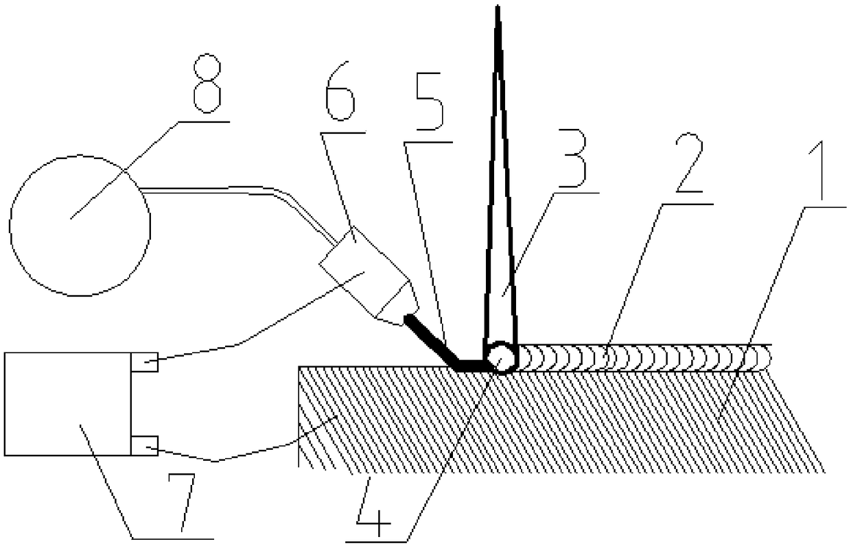
High-efficient wire material laser cladding method

A technology of laser cladding and wire materials, which is applied in laser welding equipment, welding equipment, metal processing equipment, etc., can solve the problems of low cladding efficiency and low utilization rate of laser energy, and achieve cladding efficiency improvement and line speed improvement and laser energy utilization, the effect of saving laser energy

Inactive Publication Date: 2019-03-08
SHAANXI TIANYUAN MATERIALS PROTECTION TECH
View PDF9 Cites 7 Cited by
  • Summary
  • Abstract
  • Description
  • Claims
  • Application Information

AI Technical Summary

Problems solved by technology

Therefore, the present invention effectively solves the problems of low laser energy utilization rate and low cladding efficiency in the traditional metal wire laser cladding technology, and has broad application prospects

Method used


Image

  • High-efficient wire material laser cladding method

Examples


Embodiment

[0050] Below in conjunction with embodiment, the present invention is described in further detail.

[0051] 1. This embodiment is laser cladding on the surface of the piston rod of the coal mine hydraulic support cylinder (later called the piston rod). The diameter of the piston rod is 70mm, the length of the cladding area is 1000mm, and the material is 27SiMn;

[0052] 2. The high-efficiency metal wire laser cladding scheme of the piston rod in this embodiment adopts a 4kW semiconductor fiber output laser from German Laserline Company, and the spot size formed by the laser beam on the surface of the piston rod is adjusted to be φ3mm, and the laser wavelength is 1064nm;

[0053] 3. The metal wire made of 316L solid stainless steel is selected, the cross-sectional shape of the wire is circular, and the diameter is φ1.2mm;

[0054] 4. The conductive tip is made of red copper, the wire passes through the center hole of the conductive tip, and the diameter of the center hole is 1....


PUM

PropertyMeasurementUnit
Center wavelengthaaaaaaaaaa
Section sizeaaaaaaaaaa
Diameteraaaaaaaaaa

Abstract

The invention provides a wire material laser cladding method. The wire material laser cladding method comprises the following steps that one electrode of a wire material heating device is connected with a workpiece, the other electrode of the wire material heating device is connected with a conductive nozzle, the wire material penetrates through the conductive nozzle and then makes contact with the surface of the workpiece, a laser beam and the wire material are placed in a certain angle with the surface of the workpiece respectively, the wire material heating device is started, the wire material is preheated to a certain temperature, a laser is started, and a laser beam generated by the laser is focused on wire material on the surface the workpiece, the laser energy is absorbed by the wire material, then a molten pool is instantly formed on the surface of the workpiece, the melting pool is controlled to move on the surface of the workpiece according to a preset path and a preset speed, and the laser cladding is completed. According to the method, the initial temperature and the cladding linear speed of the wire material are increased, the temperature of the wire material is increased to be close to the melting point before the wire material enters the laser beam, the wire material can melt to form a molten pool on the surface of the workpiece only by relatively small laser energy and relatively short irradiation time of the laser beam, and the wire cladding efficiency and quality are obviously improved, therefore the method has a wide popularization and application prospect.

Description

technical field [0001] The invention relates to a wire laser cladding method, in particular to a wire laser cladding method for increasing the initial temperature of the wire and the cladding line speed, and belongs to the field of advanced manufacturing technology. Background technique [0002] As an advanced manufacturing technology featuring high precision, high performance, low heat-affected zone, and low dilution rate, laser cladding technology is widely used in the preparation of modified coatings on the surface of metal parts, surface defect repair, and metal additive manufacturing. [0003] Laser cladding technology can be divided into two categories: metal powder laser cladding and metal wire laser cladding according to the state of cladding materials. Metal wire laser cladding uses metal wire as the cladding material, uses high-energy laser beams as the energy source, and melts, solidifies and deposits the metal wire and the workpiece substrate at the same time acc...

Claims


Application Information

Patent Timeline
IPC IPC(8): B23K26/342
CPCB23K26/342
Inventor 苏成明曹鹏张毅张飘飘张茅
Owner SHAANXI TIANYUAN MATERIALS PROTECTION TECH
Learn More