
Furnace for macromolecule waste heat energy conversion

A thermal energy conversion and polymer technology, applied in incinerators, gasification processes, energy input, etc., can solve the problem of inability to accurately predict gas production and calorific value, and analyze molecular structure, polymer waste ground state, and species one by one. Complex and other problems, to achieve the effect of small size, small amount of inorganic dust, complete combustion

Pending Publication Date: 2019-01-25
西安奥泽热能工程有限责任公司
View PDF0 Cites 0 Cited by
  • Summary
  • Abstract
  • Description
  • Claims
  • Application Information

AI Technical Summary

Problems solved by technology

[0003] The ground state and variety of polymer waste are complex, and the composition of materials input into each furnace is changing. It is impossible to analyze its molecular structure one by one. In actual work, it is even impossible to accurately predict its gas production and calorific value. The physical state of the currently incinerated material determines the operation mode of the gasification chamber and the combustion chamber

Method used


Image

  • Furnace for macromolecule waste heat energy conversion
  • Furnace for macromolecule waste heat energy conversion
  • Furnace for macromolecule waste heat energy conversion

Examples


Embodiment 1

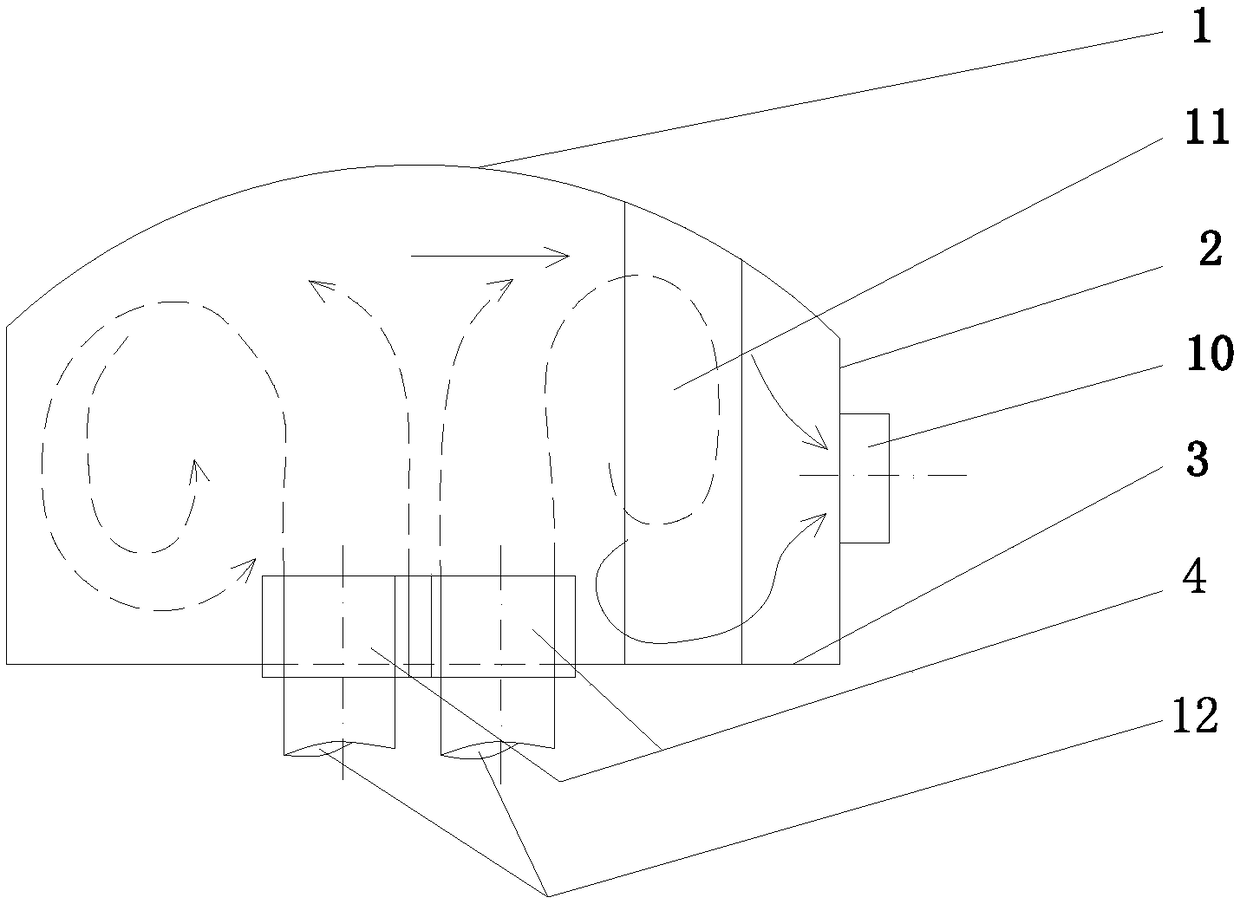
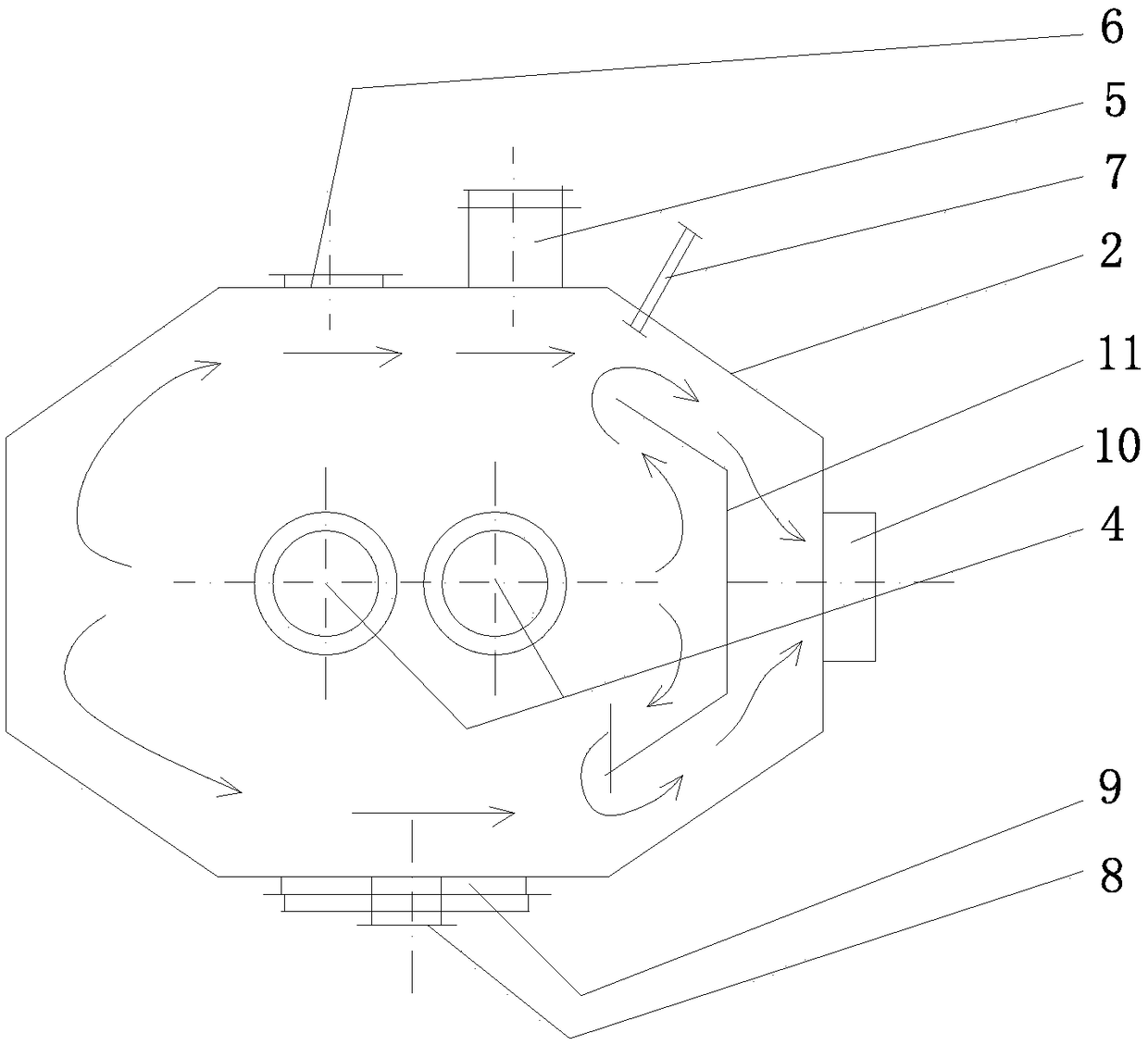
[0038] Such as figure 1 and 2 As shown, the high-temperature combustion chamber is a furnace type with a single outer volute wall and a horizontal torch nozzle. The furnace body of the high-temperature combustion chamber includes an outer volute top cover 1, an outer volute side wall 2, an outer volute bottom plate 3, and The mixer 4 and the flare outlet 10, the air pre-mixer 4 is vertically arranged in the middle of the bottom plate of the outer volute 3, and the side wall 2 of the outer volute is provided with a fuel gas machine 5 and a fuel gas machine matched with the fuel gas machine Flame nozzle cooling device, observation hole 6, detection port 7, hand hole 8 and manhole 9, said torch spout 10 is arranged laterally on the outer volute side wall 2, and the furnace body of the high temperature combustion chamber also includes a single fire retaining wall 11 , the single fire wall 11 is arranged between the air premixer 4 and the torch outlet 10, the upper end of the sing...

Embodiment 2

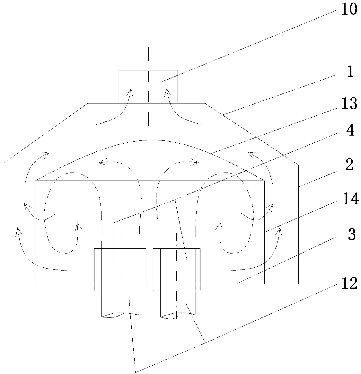
[0065] Such as image 3 and 4 As shown, the high-temperature combustion chamber is a furnace type with double outer volute walls and vertical torch outlet. The furnace body of the high-temperature combustion chamber includes the outer volute top cover 1, the outer volute side wall 2, the outer volute bottom plate 3, the The mixer 4 and the flare outlet 10, the air pre-mixer 4 is vertically arranged in the middle of the bottom plate 3 of the outer volute, and the side wall 2 of the outer volute is provided with a fuel gas engine 5 and a fuel gas engine installed with the fuel gas engine to spray fire Nozzle cooling device, observation hole 6, detection port 7, hand hole 8 and manhole 9, the torch spout 10 is erected on the outer volute top cover 1, and the furnace body of the high-temperature combustion chamber also includes an inner volute cover 13 and The inner volute side wall 14, the inner volute cover 13 is located on the upper part of the inner volute side wall 14, the i...


PUM


Abstract

The invention discloses a furnace for macromolecule waste heat energy conversion. The furnace comprises a low temperature gasification chamber and a snail cavity type high temperature combustion chamber; a furnace body of the low temperature gasification chamber is provided with a fuel gas bundling opening; a furnace body of the high temperature combustion chamber comprises an outer volute top cover, an outer volute side wall, an outer volute base plate, an air pre-mixer and a torch spraying opening, the air pre-mixer is perpendicularly arranged in the middle of the outer volute base plate, and a fuel oil machine and a fuel oil machine fire spraying nozzle cooler matched with the fuel oil machine are arranged on the outer volute side wall; the low-temperature gasification chamber is connected with the high temperature combustion chamber through the fuel gas bundling opening and the air pre-mixer; the furnace body of the high temperature combustion chamber further comprises a componentcombined with the outer volute top cover, the outer volute side wall and the outer volute base plate to form a snail cavity interior infrared light thermal irradiation focal zone and a fluid dynamic rotational flow ring region. The low temperature gasification chamber provides fuel gas flow with the low decomposition level to the high temperature combustion chamber, and the fuel gas flow is ignited under infrared light thermal irradiation at the speed of 1,000-1,500 DEG C / s to be decomposed and combusted.

Description

Technical field: [0001] The invention belongs to the technical field of thermal energy conversion and environmental protection, and in particular relates to a furnace for thermal energy conversion of polymer waste. Background technique: [0002] The common macromolecular organic pollutants in production and life mainly come from: (1) A wide variety of polymer waste or organic pollutants, for solid, liquid and viscous polymer waste such as: plastic, rubber, paint, ink, Protein, fat, cellulose, lignite, peat, asphaltene; polycyclic aromatic hydrocarbons, landing oil, oil foot, high water content sludge; and copper, aluminum, rubber and plastic wires, enameled wires, optical cables, electronic circuit boards, CDs, tapes, films , aluminum foil composite packaging, metal spray coating, etc., through the low-temperature gasification chamber to provide the gas flow of rich carbon black ions and high volatility; (2) Coal coking furnace or (blue carbon) semi-coking furnace, acetylene...

Claims


Application Information

Patent Timeline
Patent Type & Authority Applications(China)
IPC IPC(8): F23G5/027F23G5/16C10J3/72
CPCF23G5/027F23G5/16C10J3/72C10J2300/0946Y02P20/129
Inventor 许其怀
Owner 西安奥泽热能工程有限责任公司
Learn More