
A welding method for thin steel plate fillet joints

A fillet joint and welding method technology, which is applied in the welding field of thin steel plate fillet joints, can solve the problems of complex adjustment of double laser beam welding process, difficulty in mass production, and large heat input, etc., to achieve non-deformation connection, Beautiful shape and good consistency

Active Publication Date: 2021-01-26
CHANGSHA UNIVERSITY OF SCIENCE AND TECHNOLOGY
View PDF7 Cites 0 Cited by
  • Summary
  • Abstract
  • Description
  • Claims
  • Application Information

AI Technical Summary

Problems solved by technology

The invention patent published on July 13, 2018 with the publication number "CN 108274121 A" and the invention title "Double-beam laser welding machine and its welding method" discloses a double-beam laser welding process method, to a certain extent However, this technical solution still has the following problems: the adjustment of the double laser beam welding process is complicated, the heat input is large, and the deformation after welding is large
[0004] The invention patent published on July 27, 2018 with the publication number "CN 108326420 A" and the invention title "Laser Welding Forming Method for Arc Corner Joints" discloses a laser welding forming method for corner joints. To a certain extent, it solves the problem of welding and forming of thin steel plate fillet joints, but this technical solution still has the following problems: the position of the laser focal spot on the two plates and the required joint gap need to be adjusted accurately during the welding process, and the actual large-scale engineering Production is difficult to achieve

Method used


Image

  • A welding method for thin steel plate fillet joints
  • A welding method for thin steel plate fillet joints
  • A welding method for thin steel plate fillet joints

Examples


Embodiment Construction

[0039] The technical solution of the present invention will be described in detail below in conjunction with the accompanying drawings and specific embodiments.

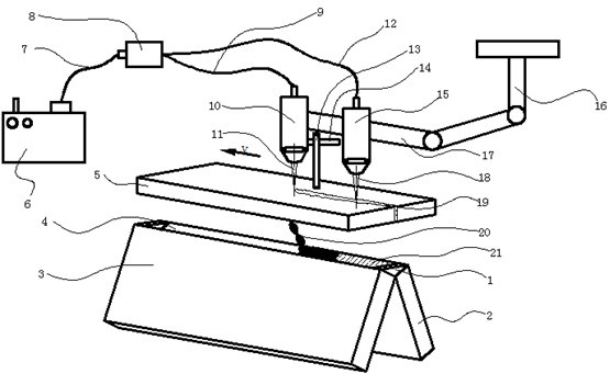
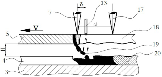
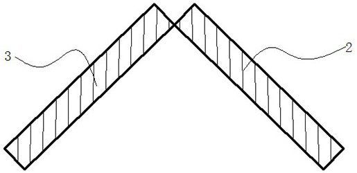
[0040] Such as Figure 1-3 As shown, the invention provides a welding method of thin steel fillet joints, comprising the steps of:

[0041] Step 1: Accurately corner-join and clamp the first workpiece 2 and the second workpiece 3 .

[0042] Optionally, the thickness of the first workpiece 2 and the second workpiece 3 are both 0.5-2.5 mm.

[0043] Optionally, the first workpiece 2 and the second workpiece 3 may be ordinary carbon steel plates, coated carbon steel plates and stainless steel plates.

[0044] Step 2: Provide a third workpiece 5 of the same material as the first workpiece 2 and the second workpiece 3, the third workpiece 5 is located directly above the corner joint.

[0045] Optionally, the thickness of the third workpiece 5 is 1.0-5.0 mm.

[0046] Optionally, the third workpiece 5 is made of the same...


PUM


Abstract

The invention relates to a welding method for a thin steel plate corner connection connector. The welding method is characterized in that firstly, a first workpiece and a second workpiece are accurately in corner connection and are clamped; secondly, a third workpiece the same with the first workpiece and the second workpiece in material is provided, and the third workpiece is located over the corner connection connector; thirdly, a laser cutting system is provided; fourthly, an air column spray gun is provided; fifthly, a laser welding system is provided; sixthly, the laser cutting system isstarted, and a first laser beam formed through focusing of a laser cutting head vertically irradiates the upper surface of the third workpiece; seventhly, the air column spray gun is started and sprays inert gases to act on metal molten drops formed through laser cutting; eighthly, the laser welding system is started, and a second laser beam is formed through focusing to irradiate filled metal inthe corner connection connector; ninthly, the laser cutting head moves to the terminal position; and tenthly, the welding process is finished. Compared with the prior art, a good welding effect is achieved, and the workpiece obtained after welding is free of deformation.

Description

technical field [0001] The invention relates to the field of welding, in particular to a welding method for fillet joints of thin steel plates. Background technique [0002] There are a large number of thin steel fillet joints in the modern high-end kitchen utensils, household appliances and other industries, which often require the weld to be beautifully formed, with good consistency, no deformation of the workpiece after welding, and a small heat-affected zone. At present, the welding forming processes for thin steel fillet joints include argon arc welding and manual spot welding. The former has a full weld seam, but has a large heat input, large welding deformation, and large welding fume; the latter has low welding efficiency and requires The amount of grinding is large and the cost is high. [0003] Laser welding has the advantages of small heat input and small deformation, which has gradually attracted the attention of manufacturers of kitchen utensils and home applia...

Claims


Application Information

Patent Timeline
Patent Type & Authority Patents(China)
IPC IPC(8): B23K3/04B23K1/00B23K3/08
CPCB23K1/00B23K3/04B23K3/08
Inventor 刘子奇张明军张远康
Owner CHANGSHA UNIVERSITY OF SCIENCE AND TECHNOLOGY
Learn More