
A kind of multifunctional laser welding method and equipment

A technology for laser welding and welding equipment, applied in the field of multi-functional laser welding methods and equipment, can solve the problems of large welding stress and deformation, single function and welding method, and high requirements for joint gaps, and achieve the goal of improving welding quality and welding efficiency. Effect

Active Publication Date: 2020-11-10
AVIC BEIJING AERONAUTICAL MFG TECH RES INST
View PDF11 Cites 0 Cited by
  • Summary
  • Abstract
  • Description
  • Claims
  • Application Information

AI Technical Summary

Problems solved by technology

[0004] Although the laser arc hybrid welding method has the lowest requirements on the joint gap, that is, the engineering adaptability is the strongest, but the fusion width of the joint is relatively wide, and the welding stress and deformation are relatively large; the fusion width of laser filler wire welding and self-fluxing laser welding Relatively narrow, high welding precision, but relatively high requirements for joint gap
In engineering applications, it is the most ideal choice to select the best laser welding method according to different assembly gaps. However, the welding methods in the prior art cannot automatically select the appropriate welding method according to the assembly gap. The existing welding equipment Low integration, single function and welding method, poor automatic performance, especially for complex structures and welding of multiple welds

Method used


Image

  • A kind of multifunctional laser welding method and equipment
  • A kind of multifunctional laser welding method and equipment
  • A kind of multifunctional laser welding method and equipment

Examples


Embodiment Construction

[0033] Embodiments of the present invention will be further described in detail below in conjunction with the accompanying drawings and examples. The detailed description and accompanying drawings of the following embodiments are used to illustrate the principles of the present invention, but cannot be used to limit the scope of the present invention, that is, the present invention is not limited to the described embodiments, without departing from the spirit of the present invention Any modification, substitution and improvement of parts, components and connection methods are covered under.

[0034] It should be noted that, in the case of no conflict, the embodiments in the present application and the features in the embodiments can be combined with each other. The present application will be described in detail below with reference to the accompanying drawings and embodiments.

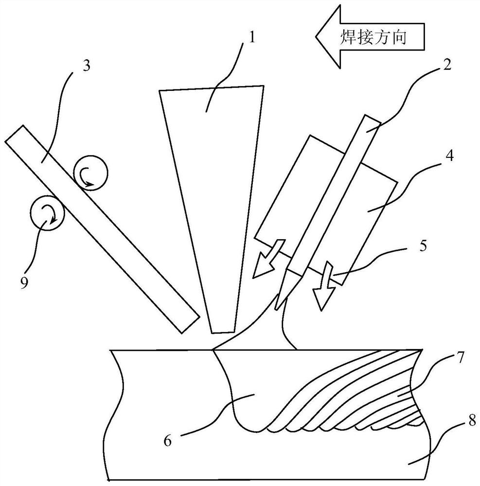
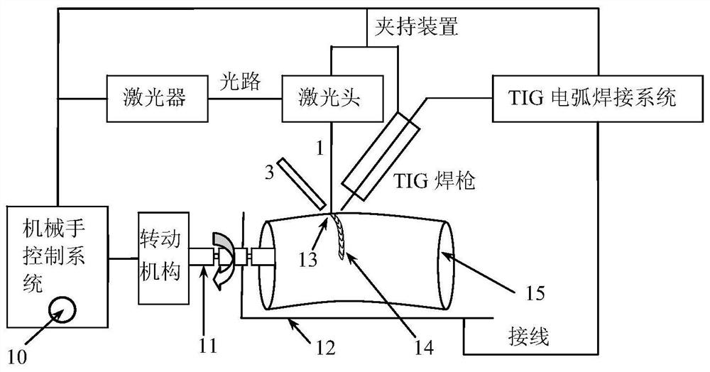
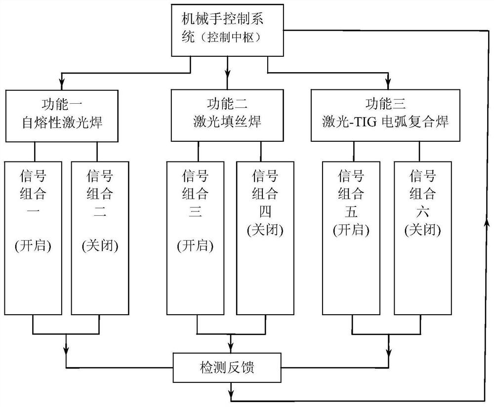
[0035] figure 1 It is a schematic diagram of the application scene of a multifunctional laser wel...


PUM


Abstract

The invention relates to multi-functional laser welding method and device. The multi-functional laser welding method comprises the steps of detecting a gap S of a welded joint through a laser head of the multi-functional laser welding device; analyzing the gap S of the welded joint through a computer software control module, controlling the multi-functional laser welding device to switch on a welding mode matched with the gap S through a manipulator control system, and when the S is smaller than 0.1mm, switching on a self-fluxing laser welding function, wherein a laser light emitting channel, a TIG shielding gas channel and a rotary mechanism are at on states; when the S is larger than or equal to 0.1 and smaller than 0.3mm, switching on a laser filler wire welding or laser-TIG electric arc hybrid welding function, wherein during laser filler wire welding, the laser light emitting channel, the TIG shielding gas channel, the rotary mechanism and a wire feeder are at on states; and when the S is larger than or equal to 0.3 and smaller than or equal to 0.5mm, switching on a laser-TIG electric arc hybrid welding function, wherein the laser light emitting channel, the TIG shielding gas channel, the rotary mechanism, the wire feeder and a TIG electric arc are at on states.

Description

technical field [0001] The invention belongs to the field of welding technology, in particular to a multifunctional laser welding method and equipment. Background technique [0002] Laser welding is based on the principle of pinhole effect, which has the advantages of low heat input, fast welding speed, small thermal deformation and residual stress, and can obtain high-quality welded joints with large depth-to-width ratios. However, self-fluxing laser welding has strict requirements on the joint gap. When the gap exceeds 10% of the base metal wall thickness or 0.1mm, whichever is smaller, it is prone to poor forming defects such as sagging. In order to reduce the joint gap margin requirements and further improve the weld shape, methods such as laser filler wire welding and laser hybrid welding have emerged as the times require. Laser wire filler welding is a welding method that fills the molten pool with welding wire during the laser welding process. Laser arc hybrid weldi...

Claims


Application Information

Patent Timeline
Patent Type & Authority Patents(China)
IPC IPC(8): B23K26/348B23K26/70
CPCB23K26/348B23K26/702
Inventor 许飞陈俐何恩光
Owner AVIC BEIJING AERONAUTICAL MFG TECH RES INST
Learn More