
Functional separator for improving performance of lithium-sulfur battery and lithium-sulfur battery comprising the functional separator

A lithium-sulfur battery and separator technology, applied in the field of electrochemistry, can solve the problems of reducing battery power density, hindering positive ion transmission, reducing practical application operability, etc., achieving fast migration rate, improving cycle and rate performance, poor performance, The effect of good application prospects

Active Publication Date: 2021-12-03
力源(广州)新能源科技有限公司
View PDF4 Cites 0 Cited by
  • Summary
  • Abstract
  • Description
  • Claims
  • Application Information

AI Technical Summary

Problems solved by technology

However, it can be expected that whether it is from the confinement effect of porous carbon on the positive electrode side or the ion sieving effect from the perspective of the separator, such physical barriers will also hinder the positive ion transmission (lithium ions) required by the battery, thereby reducing the battery. power density, in addition, its stability and effectiveness are also highly related to microstructure build-up, which greatly reduces the operability of practical applications

Method used


Image

  • Functional separator for improving performance of lithium-sulfur battery and lithium-sulfur battery comprising the functional separator
  • Functional separator for improving performance of lithium-sulfur battery and lithium-sulfur battery comprising the functional separator
  • Functional separator for improving performance of lithium-sulfur battery and lithium-sulfur battery comprising the functional separator

Examples


Embodiment 1

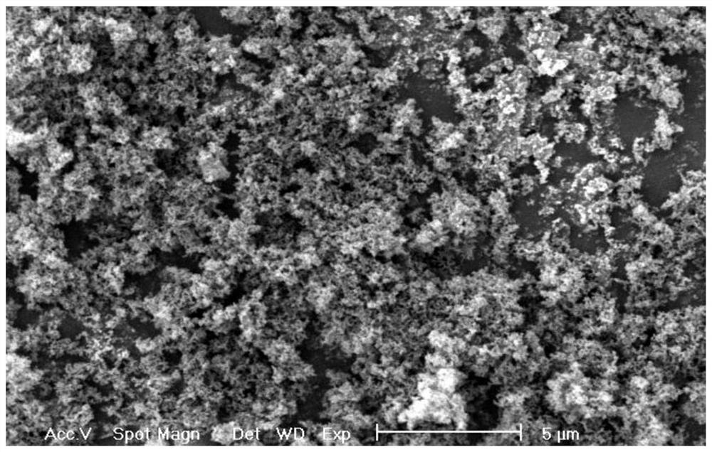
[0026] Disperse metal copper powder and carbon black with a particle size of 50 nanometers in a solution with a volume ratio of 3:1 between deionized water and acetone according to the mass ratio of 90:10, and add 6% of the total mass of the metal copper powder and carbon black. After the vinyl alcohol was mechanically stirred for 5 hours, a coating slurry was formed, and the obtained slurry was coated on one side surface of the polyethylene diaphragm on a coating machine, and the functional diaphragm was obtained after drying. The surface morphology of the functional membrane is as follows figure 1 shown.

Embodiment 2

[0028] Disperse metal copper powder and carbon nanotubes with a particle size of 1 micron in N, N dimethylformamide at a mass ratio of 95:5, and add polymethacrylic acid with a total mass of 10% of the metal copper powder and carbon nanotubes Ultrasonic dispersion after methyl ester for 2 hours to form a coating slurry, and the resulting slurry was carried out on one side surface of a polyvinylidene fluoride-hexafluoropropylene copolymer microporous polymer membrane prepared by a phase inversion method on a coating machine After coating and drying, a functional separator can be obtained.

Embodiment 3

[0030] Disperse metal copper powder, graphene, and acetylene black with a particle size of 5 microns in deionized water according to a mass ratio of 85:10:5, and add metal copper powder, graphene, and carboxymethyl fiber with 15% of the total mass of acetylene black Sodium sodium (CMC) and styrene-butadiene rubber (SBR) (the mass ratio of the two is 5:5) was dispersed by ball milling for 10 hours to form a coating slurry, which was coated on polypropylene-polyethylene- On the surface of one side of the polypropylene three-layer composite membrane, the functional membrane can be obtained after drying.


PUM

PropertyMeasurementUnit
thicknessaaaaaaaaaa
particle diameteraaaaaaaaaa

Abstract

The invention belongs to the field of electrochemistry, and specifically relates to a functional diaphragm applied to improve the electrochemical performance of lithium-sulfur batteries. By coating metal copper and conductive agents on the diaphragm, it can react with polysulfide ions and make it stable as a positive electrode. The functional separator of the active material can greatly improve the cycle stability of the lithium-sulfur battery. In addition, the construction of the functional separator can only be realized by highly commercial methods such as coating and sputtering. The preparation process is simple and is very suitable for large-scale mass production applications.

Description

technical field [0001] The invention belongs to the field of electrochemistry, and specifically relates to a functional separator applied to improve the electrochemical performance of a lithium-sulfur battery, and the invention also relates to a lithium-sulfur battery comprising the above-mentioned functional separator. Background technique [0002] At present, lithium-ion batteries are widely used in digital products and electric vehicles and are power batteries with the best comprehensive performance. Manned aircraft and other technological development requirements. Therefore, the development of secondary batteries with higher specific energy has become a common challenge faced by the international community. The theoretical specific energy of lithium-sulfur batteries is as high as 2600Wh / kg, and the actual specific energy has exceeded 350Wh / kg. It is considered to be the closest commercial high specific energy secondary battery system after lithium-ion batteries. The po...

Claims


Application Information

Patent Timeline
Patent Type & Authority Patents(China)
IPC IPC(8): H01M50/431H01M50/449H01M10/0525H01M10/42
CPCH01M10/0525H01M10/4235H01M50/446Y02E60/10
Inventor 陈栩李周江映德
Owner 力源(广州)新能源科技有限公司
Learn More